Developer Guide
FPGA Optimization Guide for Intel® oneAPI Toolkits
A newer version of this document is available. Customers should click here to go to the newest version.
Buffered Host-Device Streaming
In this topic, you learn how to optimize a full system design that streams data from the host to the device and back to the host and create heterogeneous designs that can achieve high throughput. The techniques described in this topic are not specific to a CPU-FPGA system, and you can apply them to GPUs, multi-core CPUs, and other processing units as well.
Prior to learning about buffered host-device streaming concept, you must review the following concepts:
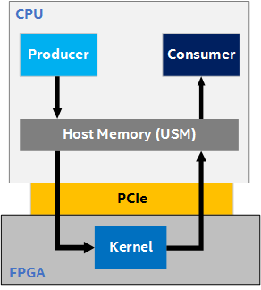
To understand the concept of buffered host-device streaming, consider an example design where a Producer (running on the CPU) produces data into USM host allocations, a Kernel (running on the FPGA) processes this data and produces output into host allocations, and a Consumer (running on the CPU) consumes the data. Data is shared between the host and FPGA device via host pointers (pointers to USM host allocations).

In heterogeneous systems, it is important to understand how different compute architectures are connected (that is, how data is transferred from one to another) to better reason about and address performance bottlenecks in the system. The following figure is a slightly more detailed illustration of the processing pipeline in the example design, which shows the data flow between the Producer, Kernel, and Consumer. It illustrates that the Producer and Consumer operations both execute on the CPU and communicate with the FPGA kernel over a PCIe link (PCIe Gen3 x16).
Roofline Analysis
When designing for throughput, you must first estimate the maximum throughput the system is capable of. This back-of-the-envelop calculation is called roofline analysis. To calculate the maximum achievable throughput of the Producer-Kernel-Consumer design shown in Figure 2, assume that the Producer and Consumer have infinite bandwidth (that is, they can produce or consume data at an infinite rate, respectively). Then, the bottleneck in the system is the FPGA kernel. Assume that the kernel has an fMAX of 400MHz and processes 64 bytes per cycle. The following is kernel's maximum steady-state throughput:
400 MHz * 64 bytes/cycle = 25.6 GB/s ~= 26 GB/s.
In reality, the rate of data transfer to and from the kernel depends on the bandwidth of the PCIe link. In Figure 2, you can observe that this depends on the bandwidth of the PCIe link. It has been experimentally measured that the PCIe Gen3 x16 link has a total bandwidth of ~22 GB/s (11 GB/s bidirectional). This means that, while the kernel can process data at 26 GB/s, you can only send data to it and receive from it at a rate of 11 GB/s. The system bottleneck is the PCIe link between the CPU and FPGA. It is common for the bottleneck in a heterogeneous system to be the inter-device link, rather than any single device.
In this analysis so far, you assumed that the Producer and Consumer had infinite bandwidth. You can now perform a roofline analysis on the entire system by assuming a finite bandwidth for the Producer and Consumer. For the entire Producer-Kernel-Consumer design, the maximum possible throughput is the minimum of the Producer, Kernel, and Consumer throughput, and the bandwidth of the link (in this case, PCIe) connecting the CPU and FPGA (a chain is only as strong as the weakest link).
Optimizing the Design for Throughput
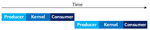
A naive approach to this design is for the Producer, Kernel, and Consumer to run sequentially that is depicted by the following timing diagram. This naive approach underperforms because operations, which could run in parallel, are run sequentially. For example, in the following figure, the Producer could be producing the second set of data, while the Consumer is consuming the first set of data:
To improve the performance, you can create a separate CPU thread (called the Producer thread) that produces all of the data for the Kernel to process, and consumes later as shown in the following figure. This allows the Producer and Consumer to run in parallel (that is, the Producer thread produces the next set of data, while the Consumer consumes the current data).
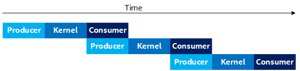
This approach improves the design's throughput, but does require more complicated thread synchronization logic to synchronize between the Producer thread and the main thread that is launching kernels and consuming its output.
Observe that in the Figure 4, the Producer and Consumer are running simultaneously (in separate threads). You must consider the fact that both of these processes are running on the CPU in parallel, which affects their individual throughput capabilities. For example, running these processes in parallel can result in saturating the CPU's memory bandwidth, and therefore lower the overall throughput for the Producer and Consumer processes even if the threads run on different CPU cores.
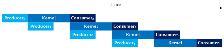
By putting the Producer into its own thread, you can improve performance by producing and consuming data simultaneously. However, it is ideal if the Producer can produce the next set of data while the kernel is processing the current data. This allows the next kernel to launch as soon as the current kernel finishes, instead of waiting for the Producer to finish, as shown in Figure 4. Unfortunately, you cannot produce data into the buffer that the kernel is currently processing, since it is still in use by the kernel. To address this, use multiple buffers (that is, N-Way buffering) of the input and output buffers, which results in a timing diagram, as shown in the following:
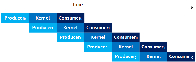
The subscript number on the Producer and Consumer (for example, Producer0 and Consumer0) represents the buffer index they are processing. The Figure 5 illustrates the case where you use two sets of buffers (double-buffering). Observe that in Figure 5, the Producer produces into buffer 1 (Producer1) while the kernel is processing the data from buffer 0. Thus, by the time the kernel finishes processing buffer 0, it can start processing buffer 1 right away, so long as the Producer has finished producing the next buffer of data.
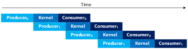
In the steady-state for Figure 5, the throughput of the design is bottlenecked by the throughput of the slowest stage (the Producer, Kernel, or Consumer), which matches the Roofline Analysis you did earlier. For example, the Figure 6 shows an example timeline where the Kernel is the throughput bottleneck. The Figure 7 shows an example timeline where the Producer (or Consumer) is the bottleneck.
Streaming API
In the Buffered Host-Device Streaming example on GitHub, the techniques described in the previous section are implemented in two ways. The design is implemented directly using SYCL USM host allocations and C++ multithreading, and the kernel queue is managed intelligently. The code achieves high performance, but it might be difficult to understand and extend it to different designs. To address this, a convenient and performant API wrapper (HostStreamer.hpp) is created. The same design is implemented in streaming_with_api.hpp with similar performance and significantly less code that is much easier to understand.
While the code that uses the HostStreamer API achieves similar performance to a direct implementation, it uses extra FPGA resources. The direct implementation has a single kernel (Kernel) that does all the processing. Using the API creates a Producer and Consumer kernel that access host allocations and produce/consume data to/from the processing kernel (APIKernel in streaming_with_api.hpp). These extra kernels (that are transparent) are the mechanism by which the API abstracts the production/consumption of data, but come at the cost of extra FPGA resources. However, when compiled for the Intel FPGA PAC D5005, these extra kernels result in less than 1% increase in FPGA resource utilization. Therefore, given the programming convenience they provide, the tradeoff is often worth it.