GTS Dynamic Reconfiguration Controller IP User Guide: Agilex™ 5 FPGAs and SoCs
ID
849710
Date
10/22/2025
Public
1. Overview
2. Quick Start Guide
3. Configuring and Generating the IP
4. Integrating the GTS Dynamic Reconfiguration Controller IP With Your Application
5. Designing with the IP Core
6. Designing the IP Solution
7. Sharing Clocking and Applying SDC Constraints
8. Runtime Flow
9. Simulating the IP
10. Validating the IP
11. Appendix A: Functional Description
12. Registers
13. Document Revision History for the GTS Dynamic Reconfiguration Controller IP User Guide
3.1. Configuring the Quartus® Prime Pro Edition Project
3.2. Generating Dynamic Reconfiguration Design and Configuration Profiles
3.3. Generating HDL for Synthesis and Simulation
3.4. Using the HSSI Support Logic Assignment Editor
3.5. HSSI Support Logic Generation
3.6. Generating the Design Example
3.7. Compiling the Design Example
9.1. Design Example Features
9.2. Simulating the GTS PMA/FEC Direct PHY Altera FPGA IP Example Design Testbench
9.3. Simulating the Ethernet to CPRI Dynamic Reconfiguration Altera FPGA IP Design Example Testbench
9.4. Simulating the GTS PTP/CPRI Multirate FPGA IP Design Example Testbench
9.5. Simulating the GTS Triple-Speed Ethernet (TSE)/Multirate Ethernet IP Design Example Testbench
10.1. Testing the Hardware Design Example for PMA Direct PHY Multirate
10.2. Testing the Hardware Design Example for Ethernet to CPRI
10.3. Testing the Hardware Design Example for PTP/CPRI Multirate
10.4. Testing the Hardware Design Example for TSE/Multirate Ethernet
10.5. Troubleshooting and Debugging Issues
12.1.1. Register Next ID Configuration 0
12.1.2. Register Next ID Configuration 1
12.1.3. Register Next ID Configuration 2
12.1.4. Register Next ID Configuration 3
12.1.5. Register Next ID Configuration 4
12.1.6. Register Next ID Configuration 5
12.1.7. Register Next ID Configuration 6
12.1.8. Register Next ID Configuration 7
12.1.9. Register Next ID Configuration 8
12.1.10. Register Next ID Configuration 9
12.1.11. Register Next ID Configuration 10
12.1.12. Register Next ID Configuration 11
12.1.13. Register Next ID Configuration 12
12.1.14. Register Next ID Configuration 13
12.1.15. Register Next ID Configuration 14
12.1.16. Register Next ID Configuration 15
12.1.17. Register Next ID Configuration 16
12.1.18. Register Next ID Configuration 17
12.1.19. Register Next ID Configuration 18
12.1.20. Register Next ID Configuration 19
12.1.21. Register Trigger
12.1.22. Register Trigger Status
12.1.23. Register Error Configuration
12.1.24. Register Error Status
3.2.1.1. Configuring the IP Parameters
On the GTS Dynamic Reconfiguration Controller IP tab, specify the parameters for your IP core variation. The following table lists the IP parameters for the GTS Dynamic Reconfiguration Controller IP:
Figure 4. GTS Dynamic Reconfiguration Controller IP Tab
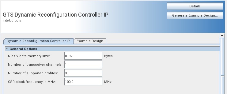
| Parameter | Range | Default Setting | Parameter Description |
|---|---|---|---|
| NIOS data memory size | 8192 - 262144 | 8192 | NIOS on-chip data memory used to store the dynamic reconfiguration data generated by Quartus® Prime in the form of a MIF file. |
| Number of transceiver channels | 1-32 | 1 | The DR controller implements one LAVMM interface, as well as one request bit and one grant bit to the channel SRC, for each transceiver channel it controls. |
| Number of Supported Profiles | 2-512 | 2 | The DR controller supports a number of profiles equal to the number of bits on the MuxSel/one-hot bus, matching the number of IP instances it controls.
Note: Each profile is one instantiated IP configuration and is assigned a unique Reconfig ID.
Note: Some IPs support a "Multi-Rate" configuration in which multiple profiles are specified within one instance. These profiles must be counted as part of the "Number of Supported Profiles" total.
|
| CSR Clock frequency in MHz | 100.0-150.0 MHz | 100 MHz | Set the frequency of the i_csr_clk input in MHz to ensure proper timer functionality. |