MIPI D-PHY IP User Guide: Agilex™ 3 and Agilex™ 5 FPGAs
ID
817561
Date
3/30/2025
Public
A newer version of this document is available. Customers should click here to go to the newest version.
1. About the MIPI D-PHY IP
2. Configuring and Generating the MIPI D-PHY IP
3. MIPI D-PHY Interface Design Guidelines
4. Simulating the MIPI D-PHY IP
5. Validating the MIPI D-PHY IP
6. Debugging the MIPI-PHY IP
7. MIPI D-PHY Architecture
8. Interface Signals and Register Maps
9. Verification Test Plan
10. Document Revision History for the MIPI D-PHY IP User Guide
6.1. Creating a Simplified Design that Demonstrates the Same Problem
6.2. Evaluating FPGA Timing Problems
6.3. Determining if the Problem Exists in Previous Quartus Prime Versions
6.4. Determining if the Problem Exists in the Current Version of Software
6.5. Verifying the MIPI D-PHY IP Using the Signal Tap Logic Analyzer
6.6. Varying the Voltage
6.7. Operating at Lower Speed
6.8. Trying a Different PCB
8.2.1.1. IP_ID
8.2.1.2. IP_CAP
8.2.1.3. D0_CAP
8.2.1.4. DN_CAP
8.2.1.5. RX_CAP
8.2.1.6. TX_CAP
8.2.1.7. TX_PREAMBLE_LEN
8.2.1.8. D-PHY_CSR
8.2.1.9. TX_CLK_LANE_PS
8.2.1.10. RX_DLANE_ERR
8.2.1.11. SKEW_CAL_LEN_B0
8.2.1.12. SKEW_CAL_LEN_B1
8.2.1.13. SKEW_CAL_LEN_B2
8.2.1.14. SKEW_CAL_LEN_B3
8.2.1.15. ALT_CAL_LEN_B0
8.2.1.16. ALT_CAL_LEN_B1
8.2.1.17. ALT_CAL_LEN_B2
8.2.1.18. ALT_CAL_LEN_B3
8.2.1.19. CLK_CSR
8.2.1.20. CLK_STATUS
8.2.1.21. DLANE_CSR_0
8.2.1.22. DLANE_STATUS_0
8.2.1.23. RX_DLANE_DESKEW_DELAY_0
8.2.1.24. RX_DLANE_ERR_0
8.2.1.25. DLANE_CSR_1
8.2.1.26. DLANE_STATUS_1
8.2.1.27. RX_DLANE_DESKEW_DELAY_1
8.2.1.28. RX_DLANE_ERR_1
8.2.1.29. DLANE_CSR_2
8.2.1.30. DLANE_STATUS_2
8.2.1.31. RX_DLANE_DESKEW_DELAY_2
8.2.1.32. RX_DLANE_ERR_2
8.2.1.33. DLANE_CSR_3
8.2.1.34. DLANE_STATUS_3
8.2.1.35. RX_DLANE_DESKEW_DELAY_3
8.2.1.36. RX_DLANE_ERR_3
8.2.1.37. DLANE_CSR_4
8.2.1.38. DLANE_STATUS_4
8.2.1.39. RX_DLANE_DESKEW_DELAY_4
8.2.1.40. RX_DLANE_ERR_4
8.2.1.41. DLANE_CSR_5
8.2.1.42. DLANE_STATUS_5
8.2.1.43. RX_DLANE_DESKEW_DELAY_5
8.2.1.44. RX_DLANE_ERR_5
8.2.1.45. DLANE_CSR_6
8.2.1.46. DLANE_STATUS_6
8.2.1.47. RX_DLANE_DESKEW_DELAY_6
8.2.1.48. RX_DLANE_ERR_6
8.2.1.49. DLANE_CSR_7
8.2.1.50. DLANE_STATUS_7
8.2.1.51. RX_DLANE_DESKEW_DELAY_7
8.2.1.52. RX_DLANE_ERR_7
8.2.1.53. TX_LPX
8.2.1.54. TX_HS_EXIT
8.2.1.55. TX_LP_EXIT
8.2.1.56. TX_CLK_PREPARE
8.2.1.57. TX_CLK_ZERO
8.2.1.58. TX_CLK_POST
8.2.1.59. TX_CLK_PRE
8.2.1.60. TX_HS_PREPARE
8.2.1.61. TX_HS_ZERO
8.2.1.62. TX_HS_TRAIL
8.2.1.63. TX_INIT
8.2.1.64. TX_WAKE
8.2.1.65. RX_CLK_LOSS_DETECT
8.2.1.66. RX_CLK_SETTLE
8.2.1.67. RX_HS_SETTLE
8.2.1.68. RX_INIT
8.2.1.69. RX_CLK_POST
8.2.1.70. RX_CAL_REG_CTRL
8.2.1.71. RX_CAL_STATUS_D-PHY
8.2.1.72. RX_CAL_SKEW_W_START_MUX
8.2.1.73. RX_CAL_SKEW_W_END_MUX
8.2.1.74. RX_CAL_ALT_W_START_MUX
8.2.1.75. RX__CAL_ALT_W_END_MUX
8.2.1.76. RX_DESKEW_DELAY_MUX
8.2.1.77. RX_CAL_STATUS_LANE_MUX
8.2.1.78. PRBS_INIT_0
8.2.1.79. PRBS_INIT_1
8.2.1.80. PRBS_INIT_2
8.2.1.81. PRBS_INIT_3
8.2.1.82. PRBS_INIT_4
8.2.1.83. PRBS_INIT_5
8.2.1.84. PRBS_INIT_6
8.2.1.85. TX_TM_CONTROL
8.2.1.86. TX_MNL_IO_0
8.2.1.87. TX_MNL_D_LP_EN
8.2.1.88. RX_TM_CONTROL
8.2.2.1. TG_TOP_CTRL_0
8.2.2.2. TG_TOP_CTRL_1
8.2.2.3. TG_TOP_DONE
8.2.2.4. TG_TOP_FAIL
8.2.2.5. TG_TOP_TEST_EN
8.2.2.6. TG_TOP_TEST_LINK
8.2.2.7. TARGET_TEST_CNT
8.2.2.8. TCHK_CONTROL
8.2.2.9. TCHK_LINK_STATUS
8.2.2.10. HS_DONE_LANES
8.2.2.11. TCHK_LINK_ERR_STATUS
8.2.2.12. LANE_ERROR_SOT_LANES
8.2.2.13. CAL_ERROR_LANES
8.2.2.14. HS_ERR_LANES
8.2.2.15. HS_TEST_CNT
8.2.2.16. LPDT_TEST_CNT
8.2.2.17. TRIGGER_TEST_CNT
8.2.2.18. ULPS_TEST_CNT
8.2.2.19. TG_RX_OVRD_DATA_PAT
8.2.2.20. TG_RX_BIT_ERROR_CNT
8.2.2.21. TG_RX_HS_TXFER_CNT
8.2.2.22. TG_LINK_CONTROL
8.2.2.23. TG_INIT_CNT
8.2.2.24. TG_HS_LEN
8.2.2.25. TG_LP_LEN
8.2.2.26. TG_SKEW_CAL
8.2.2.27. TG_ALT_CAL
8.2.2.28. TG_PER_SKEW_CAL_LEN
8.2.2.29. TG_TEST_CNT
8.2.2.30. TG_OVRD_DATA_PAT
8.2.2.31. TG_TX_HS_TXFER_CNT
5.1. Adding Signal Tap Logic Analyzer to MIPI D-PHY IP Design Example
Add the Signal Tap logic analyzer to your design to monitor the test results for the MIPI D-PHY IP design example
- On the Tools menu, click Signal Tap Logic Analyzer
- In the Signal Configuration window next to the Clock box, click … (Browse Node Finder).
- Select the clk_splitter_out_clk_clk from the MIPI D-PHY IP design example
- Under Signal Configuration, specify the following settings:
- For Sample depth, select 512
- For RAM type, select Auto
- For Trigger flow control, select Sequential
- For Trigger position, select Center trigger position
- For Trigger conditions , select 1
- Add the done and fail signal from the traffic generator instance (tg_inst) from the MIPI D-PHY IP design example.
Figure 18. Example for the TX and RX links signals
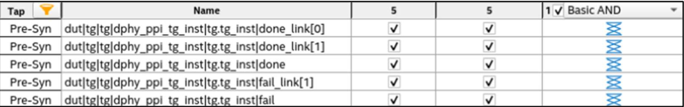
- Save the Signal Tap file by selecting File > Save
- Select Yes on the message of Do you want to enable Signal tap file “<name>.stp” for the current project?
- Run a full design compilation to generate the .sof file.