A newer version of this document is available. Customers should click here to go to the newest version.
2.3.3. Active Serial (AS) Configuration
This topic describes key differences in Active Serial (AS) configuration between Cyclone® V and Agilex™ 5 devices.
| Configuration Pin Name – Cyclone® V | Configuration Pin Name – Agilex™ 5 | Notes |
|---|---|---|
| DCLK | SDM_IO2 (AS_CLK) | When using the internal oscillator in the AS mode, the AS_CLK runs in the range of 57 - 115 based on the AS_CLK selection. If you provide a 25 MHz, 100 MHz, or 125 MHz clock to the OSC_CLK_1 pin, the AS_CLK can run up to 166 MHz. |
| AS_DATA0_ASDO AS_DATA[3:1] |
SDM_IO4 (AS_DATA0) SDM_IO6 (AS_DATA3) SDM_IO3 (AS_DATA2) SDM_IO1 (AS_DATA1) |
Agilex™ variants no longer support AS x1. They only support AS x4. |
| nCSO | SDM_IO8 (AS_nCSO3) SDM_IO7 (AS_nCSO2) SDM_IO9 (AS_nCSO1) SDM_IO5 (AS_nCSO0) |
Agilex™ devices support up to four cascaded configuration devices. |
| Not supported | SDM_IO15 (AS_nRST) | Quad SPI (QSPI) reset pin must be connected to AS_nRST pin and fully controlled by SDM. Do not connect the QSPI reset pin to any external host. |
The following are other key difference to consider for AS configuration:
- Agilex™ 5 device supports only the AS x4 mode and not support the AS x1 configuration mode.
- For JTAG Indirect Configuration File (.jic) programming, an Agilex™ 5 device uses a helper image to provide the SDM firmware and Cyclone® V requires the Serial Flash Loader IP to facilitate programming of flash over JTAG. Use the Programming File Generator tool to generate the configuration image for Agilex™ 5 device and Convert Programming Files tool for Cyclone® V device.
- For Programmer Object File (POF) programming via AS pins, set MSEL to the JTAG mode to tristate the AS interface.
- AS configuration does not retry once the configuration fails. Toggle nCONFIG to restart the configuration if necessary.
- Generic QSPI flash support is enabled to support any QSPI flash that supports the Serial Flash Discovery Parameter (SFDP) standard and dedicated reset pin. With Agilex™ 5 device, you can use the QSPI flash that supports 3-byte or 3-byte and 4-byte addressing. QSPI flash that supports 3-byte and 4-byte addressing must by default support 3-byte addressing.
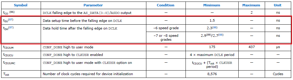
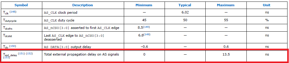
- Input DATA setup or hold time specification in Cyclone® V AS timing specifications no longer applies to Agilex™ 5 device. Hence, the timing analysis for the input DATA setup or hold time analysis in Agilex™ 5 device is not required. In Agilex™ 5, you must meet the total external propagation delay on AS signals (Text_delay) specification to meet the input DATA setup or hold time required by the AS_DATA pins. For example:
Cyclone® V AS timing specification:
Text_delay specification in Agilex™ 5 AS timing specification:
For additional information, refer to the "Active Serial Configuration" section in the Cyclone® V Device Handbook: Volume 1: Device Interfaces and Integration and Device Configuration User Guide: Agilex™ 5 FPGAs and SoCs.