External Memory Interfaces Agilex™ 7 M-Series FPGA IP Design Example User Guide
ID
772632
Date
4/01/2024
Public
A newer version of this document is available. Customers should click here to go to the newest version.
1. About the External Memory Interfaces Agilex™ 7 M-Series FPGA IP
2. Design Example Quick Start Guide for External Memory Interfaces Agilex™ 7 M-Series FPGA IP
3. Design Example Description for External Memory Interfaces Agilex™ 7 M-Series FPGA IP
4. Document Revision History for External Memory Interfaces Agilex™ 7 M-Series FPGA IP Design Example User Guide
2.1. Creating an EMIF Project
2.2. Generating and Configuring the EMIF IP
2.3. Configuring DQ Pin Swizzling
2.4. Generating the Synthesizable EMIF Design Example
2.5. Generating the EMIF Design Example for Simulation
2.6. Pin Placement for Agilex™ 7 M-Series EMIF IP
2.7. Compiling the Agilex™ 7 M-Series EMIF Design Example
2.8. Using the EMIF Design Example with the Test Engine IP
2.9. Generating the EMIF Design Example with the Performance Monitor
2.1.1.3.1. Generating a Custom Memory Preset File for DDR4
2.1.1.3.2. Guidelines for Selecting the DDR4 DRAM Component Package Type
2.1.1.3.3. Generating a Custom Memory Preset File for DDR5
2.1.1.3.4. Guidelines for Selecting the DDR5 DRAM Component Package Type
2.1.1.3.5. Generating a Custom Memory Preset File for LPDDR5
2.3.1. Example: DQ Pin Swizzling Within DQS group for x32 DDR4 interface
2.3.2. Example: Byte Swizzling for a x32 DDR4 interface, using a memory device of x8 width
2.3.3. Combining Pin and Byte Swizzling
2.3.4. Example: Swizzling for a x32 + ECC interface
2.3.5. Example: Byte Swizzling for Lockstep Configuration
2.4. Generating the Synthesizable EMIF Design Example
For the Agilex™ 7 M-Series development kit, it is sufficient to leave most of the Agilex™ 7 M-Series EMIF IP settings at their default values. To generate the synthesizable design example, follow these steps:
- On the Example Design tab, ensure that the Synthesis box is set as True.
- If you are implementing a single interface example design, configure the EMIF IP and click File > Save to save the current settings into the IP variation file (<user instance name>.ip).
Figure 30. Saving the Current Settings
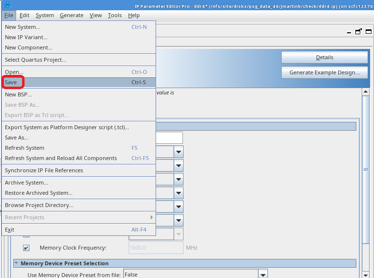
- If you are implementing a single interface example design, configure the EMIF IP and click File > Save to save the current settings into the IP variation file (<user instance name>.ip).
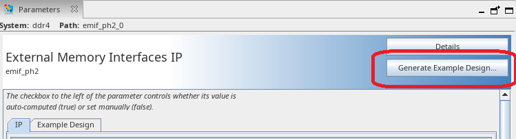
- Click Generate Example Design in the upper-right corner of the window.
Figure 31. Generate Example Design
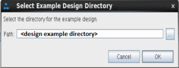
- Specify a directory for the EMIF design example and click OK. Successful generation of the EMIF design example creates the synthesis file set under a qii directory.
Figure 32. Specifying a Directory
- Click File > Exit to exit the IP Parameter Editor Pro window. The system prompts, Recent changes have not been generated. Generate now? Click No to continue with the next flow.
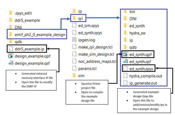
- To open the example design, click File > Open Project, and navigate to the <project_directory>/<design_example_name>/qii/ed_synth.qpf and click Open.
Note: For information on compiling and programming the design example, refer to Compiling and Programming the Agilex™ 7 M-Series EMIF Design Example .Figure 33. Generated Synthesizable Design Example File Structure
Note:
- For information on constructing a system with two or more external memory interfaces, refer to Creating a Design Example with Multiple EMIF Interfaces, in the External Memory Interfaces Agilex™ 7 M-Series FPGA IP User Guide.
- For information on debugging multiple interfaces, refer to Enabling the EMIF Toolkit in an Existing Design, in the External Memory Interfaces Agilex™ 7 M-Series FPGA IP User Guide.
- If you don't specify Simulation or Synthesis from the dropdown menu, the destination directory contains only Platform Designer design files, which the Quartus® Prime software cannot compile directly, but which you can view or edit in the Platform Designer. In this situation you can run the following commands to generate synthesis and simulation file sets:
- To create an Quartus® Prime software-compilable project, run the
quartus_sh -t make_qii_design.tcl
script in the destination directory. - To create a simulation project, run the
quartus_sh -t make_sim_design.tcl
script in the destination directory.
- To create an Quartus® Prime software-compilable project, run the
- If you have generated a design example and then make changes to it in the parameter editor, you must regenerate the design example to see your changes implemented. The newly generated design example does not overwrite the existing design example files.