1.2. Generating the Design
Prerequisite: Once you receive the eCPRI web-core IP, save the web-core installer to the local area. Run the installer with Windows/Linux. When prompted, install the web-core to the same location as Intel Quartus Prime folder. The eCPRI Intel FPGA IP now appears in the IP Catalog.
If you do not already have an Intel® Quartus® Prime Pro Edition project in which to integrate your eCPRI Intel® FPGA IP core, you must create one.
- In the Intel® Quartus® Prime Pro Edition software, click to create a new Intel® Quartus® Prime project, or click to open an existing Intel® Quartus® Prime project. The wizard prompts you to specify a device.
- Specify the device family and a device that meets the speed grade requirements.
- Click Finish.
- In the IP Catalog, locate and double-click eCPRI Intel FPGA IP. The New IP Variant window appears.
Follow these steps to generate the eCPRI IP hardware design example and testbench:
- In the IP Catalog, locate and double-click eCPRI Intel FPGA IP. The New IP Variant window appears.
- Click OK. The parameter editor appears.
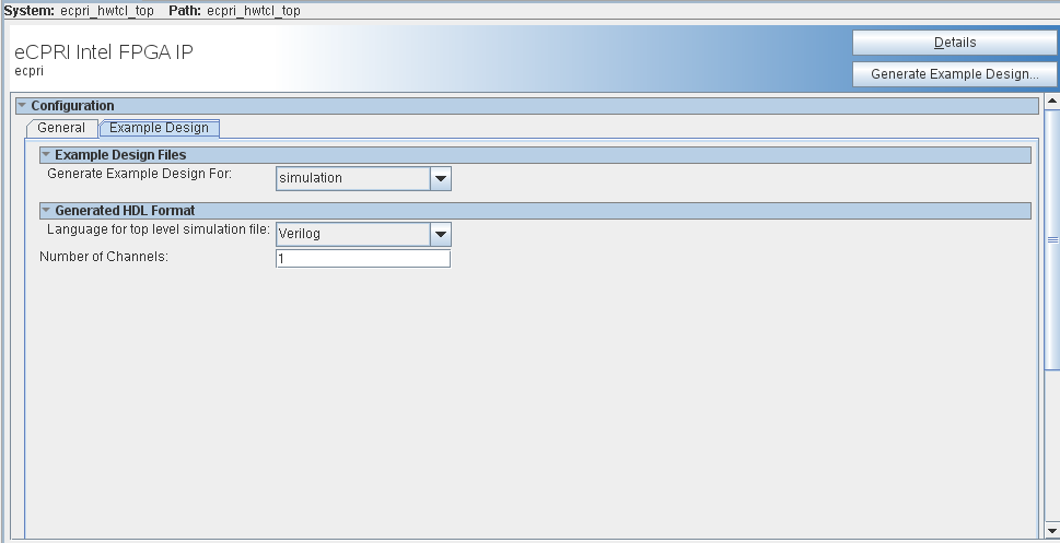
Figure 2. Example Design Tab in the eCPRI Intel FPGA IP Parameter Editor
- Specify a top-level name <your_ip> for your custom IP variation. The parameter editor saves the IP variation settings in a file named <your_ip>.ip.
- Click OK. The parameter editor appears.
- On the General tab, specify the parameters for your IP core variation.
Note:
- You must turn on Streaming parameter in the eCPRI IP parameter editor when you generate the design example with Interworking Function (IWF) Support parameter enabled,
- You must set the CPRI Line Bit Rate (Gbit/s) to Others when generating the design example with Interworking Function (IWF) Support parameter enabled.
- On the Example Design tab, select the simulation option to generate the testbench, select the synthesis option to generate the hardware example design, and select synthesis and simulation option to generate both the testbench and the hardware design example.
- For Language for top level simulation file, select Verilog or VHDL.
Note: This option is available only when you select Simulation option for your example design.
- For Language for top level synthesis file, select Verilog or VHDL.
Note: This option is available only when you select Synthesis option for your example design.
- For Number of Channels, you can enter the number of channels (1 to 4) intended for your design. Default value is 1.
- Click Generate Example Design. The Select Example Design Directory window appears.
- If you want to modify the design example directory path or name from the defaults displayed (ecpri_0_testbench), browse to the new path and type the new design example directory name.
- Click OK.