4.12. Arria® 10 EPE - Report Worksheet
| Input Parameter | Description |
|---|---|
| Power Rail Configuration | Selects a power rail configuration for assignment of supply rails to regulator groups. This field is enabled regardless of the Power Characteristics setting in the Main worksheet. You will receive a warning message if you select a power rail configuration when the Power Characteristics setting is Typical. Choose Custom to manually enter regulator group selection, or to modify the results of automatic selection. |
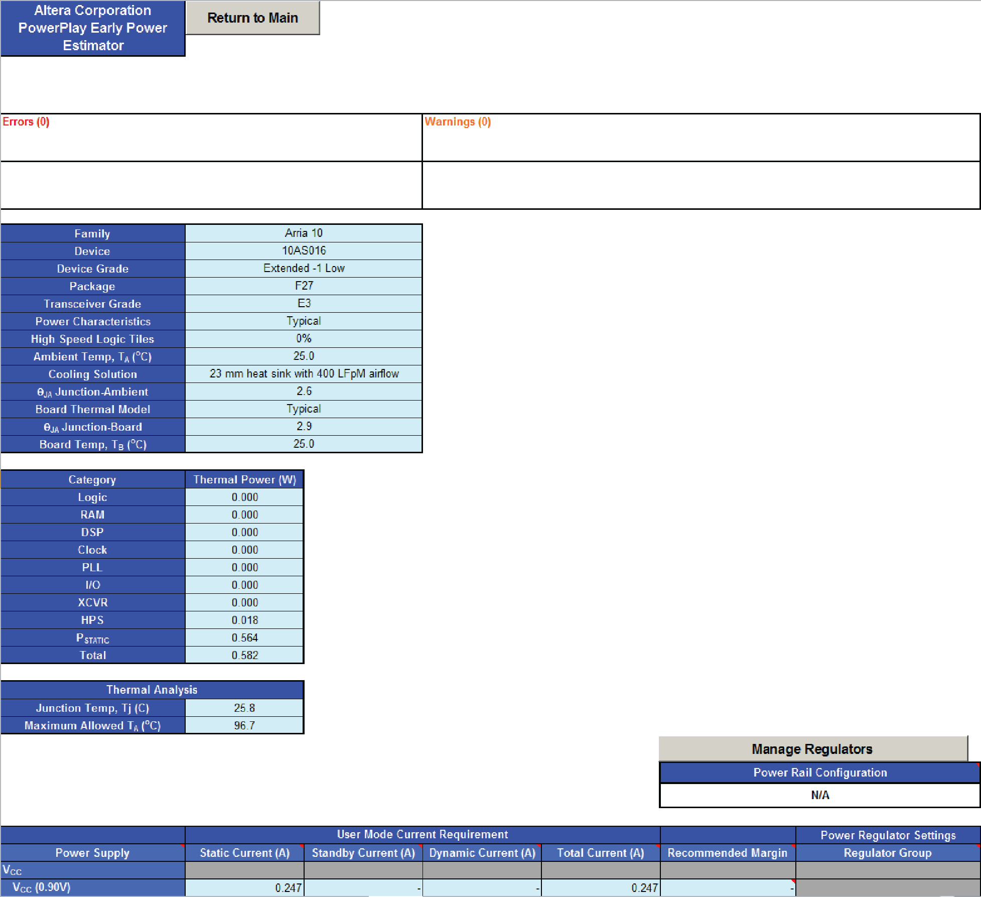
The Report worksheet provides current requirements for each voltage rail, expressed in terms of static current, standby current, dynamic current, and total current.
| Module | Parameter | Description |
|---|---|---|
| User Mode Current Requirement | Power Supply | Indicates the power supply rail name and voltage applied to the specified rail (in V). |
| Static Current (A) | Indicates the component of current consumed from the specified power rail whenever the power is applied to the rail, independent of circuit activity (in A). This current is dependent on device size, device grade, power characteristics and junction temperature. | |
| Standby Current (A) | Indicates the component of active current drawn from the specified power rail by all modules on all worksheets, independent of signal activity (in A). This current is independent of device grade, power characteristics and junction temperature. Standby current includes, but is not limited to, I/O and transceiver DC bias current. Device size has only a small impact on transceiver DC bias current. | |
| Dynamic Current (A) | Indicates the component of active current drawn from the specified power rail due to signal activity of all modules on all worksheets (in A). This current depends on device size, but is independent of device grade, power characteristics and junction temperature. | |
| Total Current (A) | Indicates the total current consumed from the specified power rail (in A). This value is the sum of static, standby and dynamic current. | |
| Recommended Margin | The recommended margin on Total Current estimates to use for regulator sizing due to possible inaccuracies in the power model. The Recommended Margin percentage represents a model accuracy such that >95% of designs fall within the Recommended Margin of silicon. To enable display of the recommended margin, Power Characteristics on the Main worksheet must be set to Maximum. Final power models are correlated with measured silicon results using thousands of designs. (Refer to the Main worksheet for the Power Model status for a given device). For the Vcc rail, a design-specific margin is provided. This margin is calculated based on the ratio of static to dynamic power because static power is reported as a limit and only the dynamic power portion has recommended margin. For all other rails, the recommended margin is a static value. |
|
| Power Regulator Settings | Regulator Group | Indicates the number of the regulator group to which this supply rail is assigned. The regulator group numbers correspond to the group numbers shown in the Enpirion worksheet. If one of the automatic assignment modes is selected in the Power Rail Configuration field, the regulator group numbers also correspond to the group numbers in the pin connection guidelines. To manually edit fields in this column, select Custom under Power Rail Configuration. Manual edits may be necessary to correct grouping errors that may result from automatic assignment. |