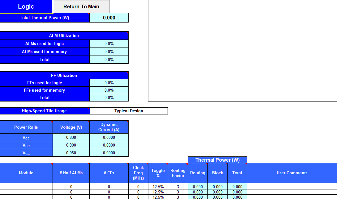
4.3. Arria® 10 EPE - Logic Worksheet
| Input Parameter | Description |
|---|---|
| High-Speed Tile Usage | Select the High-Speed Tile Usage setting. This value can be Typical Design, Typical High-Performance Design, or Atypical High-Performance Design.
This setting affects static power consumption (PSTATIC) found in the Main worksheet of the EPE spreadsheet. It also has a small impact on the dynamic power consumed by the logic resources entered in the Logic worksheet of the EPE spreadsheet.
Note: When you import a design from the Intel® Quartus® Prime software, the Early Power Estimator imports a precise value for high-speed tile usage, and the value of this setting changes to Imported.
|
| Input Parameter | Description |
|---|---|
| Module | Specify a name for each module of the design. This is an optional entry. |
| #Half ALMs | Enter twice the number of Adaptive Logic Modules (ALMs) used in your design. |
| # FFs | Enter the number of flipflops in the module. Clock routing power associated with flipflops is calculated separately on the Clock worksheet of the EPE spreadsheet. |
| Clock Freq (MHz) | Enter a clock frequency (in MHz). This value is limited by the maximum frequency specification for the device family.
Note:
When you import a design from the Intel® Quartus® Prime software, some imported half ALMs and flipflops may have a clock frequency of 0 MHz; this can occur for one of two reasons:
|
| Toggle % | Enter the average percentage of clock cycles when the block output signals change values. Toggle percentage is multiplied by clock frequency to determine the number of transitions per second. For example, 100 MHz frequency with a 12.5% toggle rate, means that each LUT or flipflop output toggles 12.5 million times per second (100MHz × 12.5%). The toggle percentage ranges from 0 to 100%. Typically, the toggle percentage is 12.5%, which is the toggle percentage of a 16-bit counter. Most logic only toggles infrequently; therefore, toggle rates of less than 50% are more realistic. To ensure you do not underestimate the toggle percentage, use a realistic toggle percentage obtained through simulation. For example, a T flipflop (TFF) with its input tied to VCC has a toggle rate of 100% because its output is changing logic state on every clock cycle. Refer to the 4-Bit Counter Example below for a more detailed analysis. For any rows containing flip-flops, toggle percentage cannot exceed 100%. A small portion of ALMs in a design may experience glitching that results in toggle percentage exceeding 100% for such ALMs. Enter such ALMs into a separate row with # FFs set to 0. |
| Routing Factor | Indicates the extent of the routing power of the outputs. Characteristics that have a large power impact and are captured by this factor include the following:
The default value for this field is typical; the actual value varies between blocks in your design, and depends on the placement of your design. For most accurate results, you should import this value from the Intel® Quartus® Prime software, because the Intel® Quartus® Prime software has access to detailed placement information. In the absence of a Intel® Quartus® Prime design, higher values generally correspond to signals that span large distances on the FPGA and fanout to many destinations, while lower values correspond to more localized signals. You can change this field from its default value to explore possible variations in power consumption depending on block placement. When changing this value, keep in mind that typical designs rarely use extreme values, and only for a small subset of the design. |
| Thermal Power (W) - Routing | Indicates the power dissipation due to estimated routing (in W). Routing power depends on placement and routing, which is a function of design complexity. The values shown are representative of routing power based on observed behavior across more than 100 real-world designs. Use the Intel® Quartus® Prime Power Analyzer for accurate analysis based on the exact routing used in your design. |
| Thermal Power (W) - Block | Indicates the power dissipation due to internal toggling of the ALMs (in W). Logic block power is a combination of the function implemented and the relative toggle rates of the various inputs. The EPE spreadsheet uses an estimate based on observed behavior across more than 100 real-world designs. Use the Intel® Quartus® Prime Power Analyzer for accurate analysis based on the exact synthesis of your design. |
| Thermal Power (W) - Total | Indicates the estimated power (in W), based on information entered into the EPE spreadsheet. It is equal to the sum of routing power and block power. |
| User Comments | Enter any comments. This is an optional entry. |
The cout0 output of the first TFF has a toggle percentage of 100% because the signal toggles on every clock cycle. The toggle percentage for the cout1 output of the second TFF is 50% because the output toggles every two clock cycles. Similarly, the toggle percentage for the cout2 and cout3 outputs are 25% and 12.5%, respectively. Therefore, the average toggle percentage for this 4-bit counter is (100 + 50 + 25 + 12.5)/4 = 46.875%.
For more information about logic block configurations, refer to the Logic Array Blocks and Adaptive Logic Modules chapter of the Arria® 10 Device Handbook.