Intel® Quartus® Prime Pro Edition User Guide: Design Optimization
A newer version of this document is available. Customers should click here to go to the newest version.
6.5.3.7. Report Pipelining Information
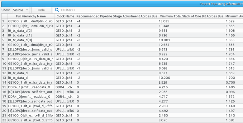
Report Pipelining Information... does not perform any functional analysis in making the recommended pipeline stage adjustment. You must be aware of any potential functional changes from removing pipeline stages. There may be circumstances when all the stages in a register pipeline are necessary for functional reasons. The report helps to identify location with more registers than necessary for covering distance.


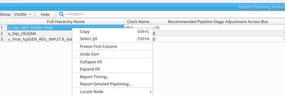
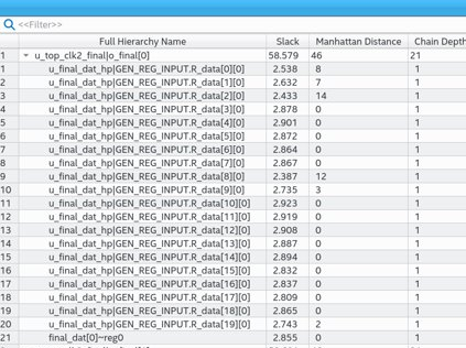
The detailed report shows every register in a tree structure. Over- or under-pipelining recommendations are in the main report. The following shows every single register inside the bus chain in a tree structure:

To help identify potential over-pipelining, Report Pipelining Information reports:
- The recommended pipeline stage adjustment across bus
- The minimum total slack of one bit across bus
- The minimum average slack of one bit across bus
- The distance between the registers
- The width of buses in your design
- The number of sequential registers
- The number of registers on the bus
The Recommended Pipeline Stage Adjustment Across Bus reports the number of registers that you can remove from the bus for each bit. The Average Distance Per Stage, Max Distance Per Stage, and Min Distance Per Stage columns report the Manhattan distance measured in logic array blocks (LABs). The Bus Average Depth, Bus Max Depth, and Bus Min Depth columns report the number of sequential, single fan-out registers. For registers that have more than one clock source, the report lists the fastest one.
The 1+ sign under Recommended Pipeline Stage Adjustment Across Bus column means that the bus might need to add more registers to meet timing requirement. Refer to the Fast Forward Timing Closure Recommendations report.
If the report identifies a large register chain with multiple sequential registers, and the distance between registers is low, that condition can suggest over-pipelining. You may be able to remove some registers to recover some of the device area and reduce congestion.
The following options are available for this report:
| Option | Available Settings |
|---|---|
| Pipeline | Specifies the thresholds for reporting a register pipeline. You can define the Minimum average bus depth, the Minimum bus width, and the Maximum number of rows that the report includes. |
| Report panel name | Specifies the name of the report panel. You can optionally enable File name to write the information to a file. If you append .htm or .html as a suffix, the Timing Analyzer produces the report as HTML. If you enable File name, you can Overwrite or Append the file with latest data. |
| Tcl command | Displays the Tcl syntax that corresponds with the GUI options you select. You can copy the command from the Console into a Tcl file. |