R-tile Avalon® Streaming Intel® FPGA IP for PCI Express* Design Example User Guide
ID
683544
Date
6/20/2022
Public
A newer version of this document is available. Customers should click here to go to the newest version.
1. About the R-tile Avalon® Streaming Intel® FPGA IP for PCI Express PIO Design Example
2. Quick Start Guide
3. R-Tile Avalon® Streaming Intel® FPGA IP for PCI Express* Design Example User Guide Archives
4. Document Revision History for the R-tile Avalon® Streaming Intel FPGA IP for PCI Express Design Example User Guide
2.4.5.1. ebfm_barwr Procedure
2.4.5.2. ebfm_barwr_imm Procedure
2.4.5.3. ebfm_barrd_wait Procedure
2.4.5.4. ebfm_barrd_nowt Procedure
2.4.5.5. ebfm_cfgwr_imm_wait Procedure
2.4.5.6. ebfm_cfgwr_imm_nowt Procedure
2.4.5.7. ebfm_cfgrd_wait Procedure
2.4.5.8. ebfm_cfgrd_nowt Procedure
2.4.5.9. BFM Configuration Procedures
2.4.5.10. BFM Shared Memory Access Procedures
2.4.5.11. BFM Log and Message Procedures
2.4.5.12. Verilog HDL Formatting Functions
2.4.5.11.1. ebfm_display Verilog HDL Function
2.4.5.11.2. ebfm_log_stop_sim Verilog HDL Function
2.4.5.11.3. ebfm_log_set_suppressed_msg_mask Task
2.4.5.11.4. ebfm_log_set_stop_on_msg_mask Verilog HDL Task
2.4.5.11.5. ebfm_log_open Verilog HDL Function
2.4.5.11.6. ebfm_log_close Verilog HDL Function
2.2. Generating the Design Example
Figure 10. Procedure
- In the Intel® Quartus® Prime Pro Edition software, create a new project (File > New Project Wizard).
- Specify the Directory, Name, and Top-Level Entity.
- For Project Type, accept the default value, Empty project. Click Next.
- For Add Files click Next.
- For Family, Device & Board Settings under Family, select Intel® Agilex™ I-Series.
- Select the Target Device for your design.
- Click Finish.
- In the IP Catalog locate and add the Intel R-Tile Avalon® -ST Hard IP for PCI Express* .
- In the New IP Variant dialog box, specify a name for your IP. Click Create.
- On the Top-Level Settings and PCIe* Settings tabs, specify the parameters for your IP variation.
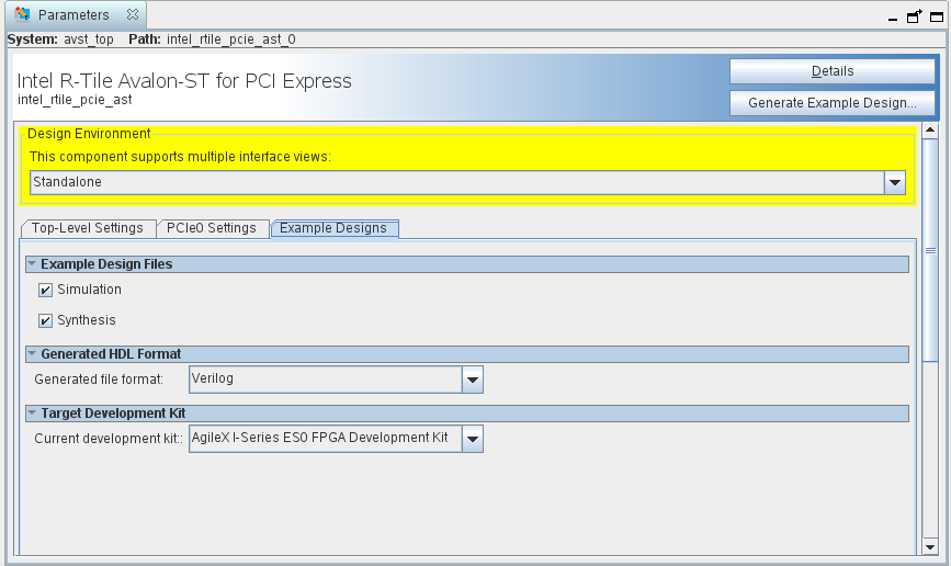
- On the Example Designs tab, make the following selections:
- For Available Example Designs, currently only PIO is available.
- For Example Design Files, turn on the Simulation and Synthesis options. If you do not need these simulation or synthesis files, leaving the corresponding option(s) turned off significantly reduces the example design generation time.
- For Generated HDL Format, only Verilog is available in the current release.
- For Target Development Kit, select the appropriate development kit.
Note: If you select None, the generated design example targets the device you specified in Step 5 above. If you intend to test the design in hardware, make the appropriate pin assignments in the .qsf file. You can also use the pin planner tool to make pin assignments.Note: Note that the current OPN for the Intel® Agilex™ I-Series Development Kit only has simulator support for Siemens EDA QuestaSim* , VCS* , and VCS* MX. For Xcelium* simulations, set this option to None and generate the design example targeting an OPN with an R2 or R3 suffix. For more details on OPN decoding, refer to the Intel® Agilex™ FPGAs and SoCs Device Overview.Note: If you select a development kit, the device on that board overwrites the device selected in the Intel® Quartus® Prime project if the devices are different.
- Select Generate Example Design to create a design example that you can simulate. When the prompt asks you to specify the directory for your example design, you can accept the default directory, ./intel_rtile_pcie_ast_0_example_design, or choose another directory.
Figure 11. IP Parameter Editor Screen for Generating Example Design
- Click Finish. You may save your .ip file when prompted, but it is not required to be able to use the example design.
- Close the current open project.
- Open the example design project. This is the new project that has been generated in the location specified in step 12.
- Compile the example design project to generate the .sof file for the complete example design.
- Close your example design project.
Note that you cannot change the PCIe pin allocations in the Intel® Quartus® Prime project. However, to ease PCB routing, you can take advantage of the lane reversal and polarity inversion features supported by this IP.