3.2.2. Constructing the Channel
Next, construct the channel between the transmitter and receiver. In Intel® Advanced Link Analyzer, the package models for the Stratix® V GX transmitter and PCI Express* 8GT receiver are embedded. The transmitter and receiver packages are automatically included in the simulation.
Intel® Advanced Link Analyzer supports crosstalk modeling capabilities. The channel engine and simulation engine can extract and interpret crosstalk characteristics from a single or a multi-lane S-parameter file and compute the crosstalk effects. In the channel list, crosstalk channels are assumed to run in parallel with the victim channel and the crosstalk noises are superimposed. This section describes how to set up crosstalk simulation in Intel® Advanced Link Analyzer.
The backplane model is provided as a 12-port S-parameter. It consists of both insertion loss and crosstalk characteristics. However, Intel® Advanced Link Analyzer requires you to add them one at a time (even if the loss and crosstalk characteristics are from the same multiple-lane S-parameter file). Therefore, you are going to insert three channel components during channel setup: one backplane victim channel and two backplane aggressor channels.
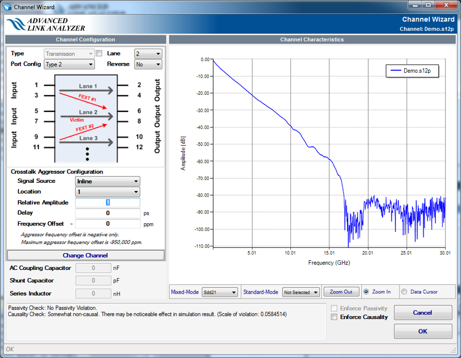
Perform the following steps to add a victim channel:
- Click Channel in the Link Designer and select Transmission.
- Use the file browser to locate the channel model file Demo.s12p and add it to the channel list as victim.
- The Intel® Advanced Link Analyzer Channel Wizard displays the Sdd21 characteristics of the middle lane (lane 2) in the 12-port S-parameter.
- Click OK to close the Channel Wizard.
- Place the channel icon in the Link Designer.
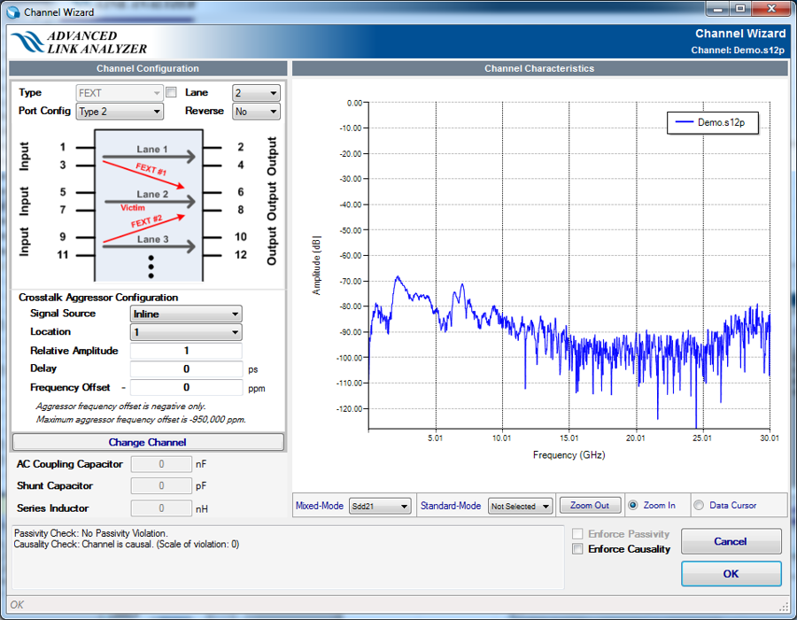
Perform the following steps to add the first crosstalk channel:
- Click Channel in the Link Designer panel and select Far-end Crosstalk (FEXT).
- Use the file browser to locate the channel model file Demo.s12p and add it to the channel list as FEXT.
- The Intel® Advanced Link Analyzer Channel Wizard displays the FEXT #1 characteristic. Note that the Crosstalk Aggressor Location 1 is selected in for this channel.
- Click OK to close the Channel Wizard.
- Place the channel icon in the Link Designer.
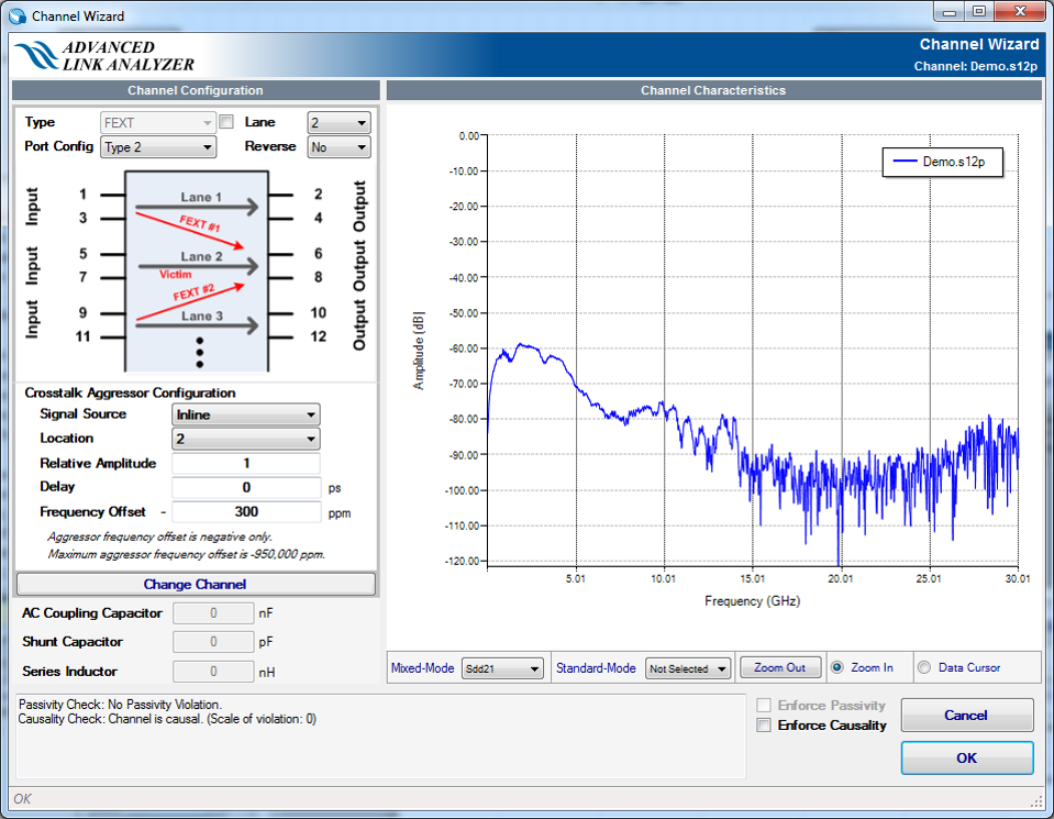
Perform the following steps to add the second crosstalk channel:
- Click Channel in the Link Designer panel and select Far-end Crosstalk (FEXT).
- Use the file browser to locate the channel model file Demo.s12p and add it to the channel list as second FEXT.
- The Intel® Advanced Link Analyzer Channel Wizard displays the first FEXT channel characteristic by default.
- Change the Crosstalk Aggressor Location to 2. This tells Intel® Advanced Link Analyzer to select the second FEXT in the12-port S-parameter.
- Set the aggressor frequency offset to 300 ppm to emulate the phase shifting effect for this crosstalk noise source. This setting indicates the 2nd crosstalk is not frequency synchronous to the victim channel.
- Click OK to close the Channel Wizard.
- Place the channel icon in the Link Designer.