A newer version of this document is available. Customers should click here to go to the newest version.
Answers to Top FAQs
1. Overview of the Intel® FPGA Power and Thermal Calculator
2. Estimating Power Consumption with the Intel® FPGA Power and Thermal Calculator
3. Intel® FPGA Power and Thermal Calculator Graphical User Interface
4. Intel® FPGA Power and Thermal Calculator Pages
5. Factors Affecting the Accuracy of the Intel® FPGA PTC
6. Intel® FPGA Power and Thermal Calculator User Guide Archive
7. Document Revision History for the Intel® FPGA Power and Thermal Calculator User Guide
A. Measuring Static Power
3.2.2.1. Using Design Hierarchies in the Intel® FPGA Power and Thermal Calculator
3.2.2.2. Entering Hierarchy Information Into the Intel® FPGA PTC
3.2.2.3. Exporting, Importing, Duplicating, Renaming, and Deleting Hierarchies in the Intel® FPGA PTC
3.2.2.4. Bulk Editing Hierarchies in the Intel FPGA PTC
4.1. Intel® FPGA PTC - Power Summary/Navigation
4.2. Intel® FPGA PTC - Common Page Elements
4.3. Intel® FPGA PTC - Main Page
4.4. Intel® FPGA PTC - Logic Page
4.5. Intel® FPGA PTC - RAM Page
4.6. Intel® FPGA PTC - DSP Page
4.7. Intel® FPGA PTC - Clock Page
4.8. Intel® FPGA PTC - PLL Page
4.9. Intel® FPGA PTC - I/O Page
4.10. Intel® FPGA PTC - Transceiver Page
4.11. Intel® FPGA PTC - HPS Page
4.12. Intel® FPGA PTC - Crypto Page
4.13. Intel FPGA PTC - NOC Page
4.14. Intel® FPGA PTC - HBM Page
4.15. Intel® FPGA PTC - Thermal Page
4.16. Intel® FPGA PTC - Report Page
3.3. Intel® FPGA PTC - IP Wizard
The IP Wizard of the Intel® FPGA Power and Thermal Calculator (PTC) allows you to select, configure, and instantiate IP blocks which are then appended to your current design.
- You can launch the IP Wizard from the PTC File menu, by clicking File > IP Wizard or clicking the IP wizard button on the toolbar.
Figure 24. Launching the IP Wizard
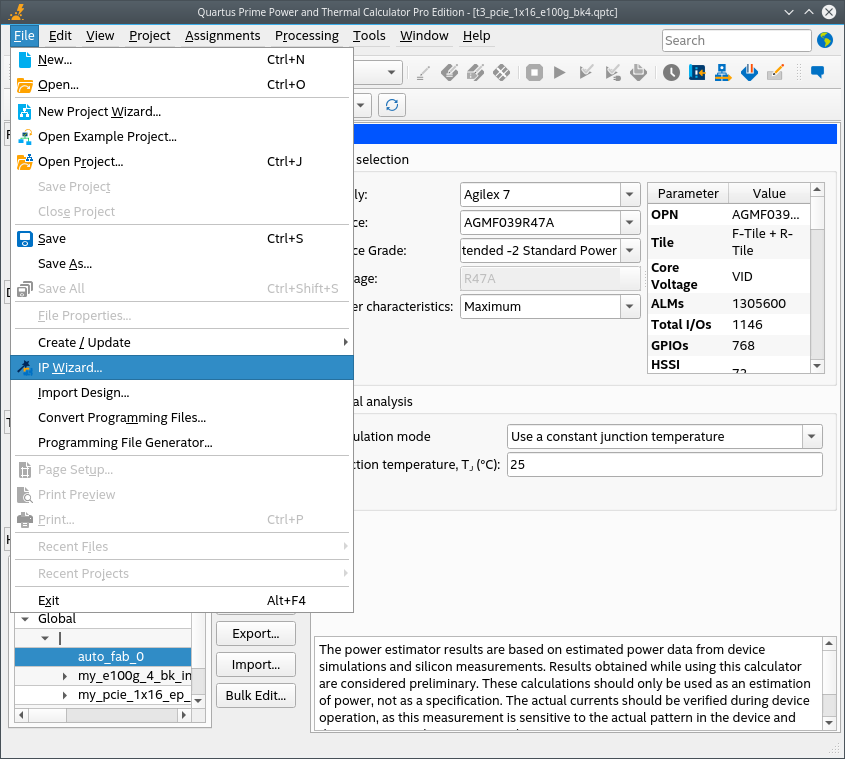 Figure 25. Launching the IP Wizard with button
 - The opening dialog box of the IP Wizard prompts you to select an IP from a pulldown list. Select the IP that you want to add to your design, and click Next.
- The IP Wizard then displays a dialog box for configuring your selected IP. Enter the appropriate information, and click Next.
Figure 27. IP Configuration PageThe IP Parameter Configuration page parameters depend on the IP you select. These parameters are a subset of the parameters in IP Catalog wizards. Refer to the appropriate IP User Guide for more details on each IP's parameters.
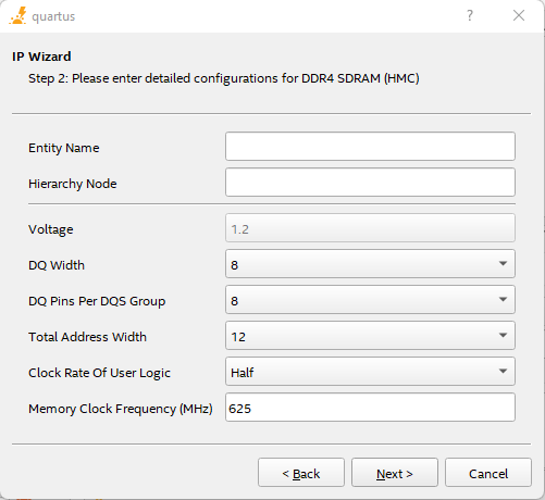
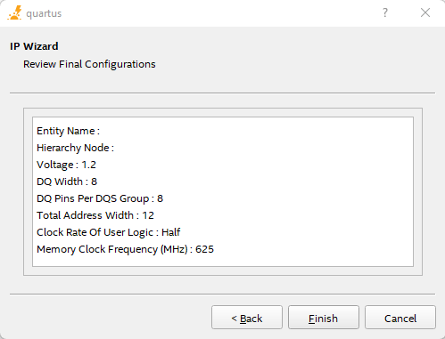
Table 8. IP Configuration FieldsThis table is only relevant for EMIF IPs in Intel Stratix 10 devices. . Column Heading Description Entity Name Specify a name for the entity. Hierarchy Node (Mandatory field) Specifies the name of the IP instance. Voltage Specifies the I/O voltage of the signaling between periphery device and interface. Data Width (Bits) Specifies the interface data width of the specific IP (in bits). Data Group Width Specifies the data group width. Memory Device(s) Specifies the number of memory devices connected to the interface. Total Address Width Specifies the total address width. This value is used to derive the total number of address pins required. DDR Rate Specifies the clock rate of user logic. Determines the clock frequency of user logic in relation to the memory clock frequency. For example, if the memory clock sent from the FPGA to the memory device is toggling at 800MHz, a "Quarter rate" interface means that the user logic in the FPGA runs at 200MHz. PHY Rate Specifies the clock rate of PHY logic. Determines the clock frequency of PHY logic in relation to the memory clock frequency. For example, if the memory clock sent from the FPGA to the memory device is toggling at 800MHz, a "Quarter rate" interface means that the PHY logic in the FPGA runs at 200MHz. Memory Clock Frequency (MHz) Specifies the frequency of memory clock (in MHz). - The IP Wizard then displays the configuration details for your review. If you want to change any of the configuration, click Back. Otherwise, if you are satisfied with the configuration, click Finish.
Figure 28. IP Configuration Review Page
After you exit the IP Wizard, the system appends new rows to the PTC pages (Logic, PLL, I/O, etc.), in accordance with the IP that you have added.