F-Tile Avalon® Streaming Intel® FPGA IP for PCI Express* Design Example User Guide
ID
683372
Date
10/04/2022
Public
A newer version of this document is available. Customers should click here to go to the newest version.
3.2. Generating the Design Example
Figure 18. Procedure
- In the Intel® Quartus® Prime Pro Edition software, create a new project (File > New Project Wizard).
- Specify the Directory, Name, and Top-Level Entity.
- For Project Type, accept the default value, Empty project. Click Next.
- For Add Files click Next.
- For Family, Device & Board Settings under Family, select Intel® Agilex™ .
- Select the Target Device for your design.
- Click Finish.
- In the IP Catalog locate and add the Intel F-Tile Avalon® -ST Hard IP for PCI Express* .
- In the New IP Variant dialog box, specify a name for your IP. Click Create.
- On the Top-Level Settings tabs, specify the parameters for your IP variation.
Note: This design example only supports the default settings in the Parameter Editor of the F-tile Avalon® Streaming IP for PCIe.If you are using the SR-IOV design example, run the following steps to enable SR-IOV:
- On the PCIe* Settings tab under the PCIe* PCI Express / PCI Capabilities tab, check the box Enable multiple physical functions.
- On the PCIe* Multifunction and SR-IOV System Settings tab, check the box Enable SR-IOV support and specify the number of PFs and VFs.
- On the PCIe* MSI-X tab under the PCIe* PCI Express / PCI Capabilities tab, enable the MSI-X feature as required.
- On the PCIe* Base Address Registers tab, enable BAR0 for both PF and VF.
- Other parameter settings are not supported for this design example.
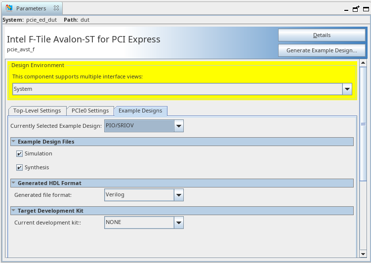
- On the Example Designs tab, make the following selections:
- For Example Design Files, turn on the Simulation and Synthesis options. If you do not need these simulation or synthesis files, leaving the corresponding option(s) turned off significantly reduces the example design generation time.
- For Generated HDL Format, only Verilog is available in the current release.
- For Target Development Kit, select either the Intel Agilex F-Series F-Tile ES FPGA Development Kit or NONE to target on the device selected for the current Quartus Prime project. If you select the development kits, the VID-related settings including the pin assignments are included in the .qsf file of the generated design example, and you are not required to add them manually. Note that these settings are board-specific.
- For Currently Selected Example Design, select PIO/SRIOV or PERFORMANCE_DESIGN.
- Select Generate Example Design to create a design example that you can simulate and download to hardware. If you select one of the F-Tile development boards, the device on that board overwrites the device previously selected in the Intel® Quartus® Prime project if the devices are different. When the prompt asks you to specify the directory for your example design, you can accept the default directory, ./pcie_avst_f_0_example_design, or choose another directory.
Figure 19. Example Designs Tab
- Click Finish. You may save your .ip file when prompted, but it is not required to be able to use the example design.