Using the Transceiver Reconfiguration Controller for Dynamic Reconfiguration in Arria V and Cyclone V Devices
ID
683321
Date
12/04/2015
Public
1.4.1. Creating the Qsys System
1.4.2. Creating the Transceiver Native PHY IP
1.4.3. Creating the Reconfiguration Controller
1.4.4. Creating the CMU PLL Using an Arria V Transceiver PLL
1.4.5. Creating a Fractional PLL (fPLL) using Altera PLL
1.4.6. Creating the Transceiver PHY Reset Controller
1.4.7. Creating a ROM that Contains the MIF for Reconfiguration
1.4.8. Compiling the Design Example
1.4.9. Creating In-System Sources and Probes (ISSP)
1.4.10. Performing Reconfiguration with the System Console Tool
1.4. Arria V GX Dynamic Reconfiguration Design Example
The design example uses the Reconfiguration Controller to dynamically reconfigure a Native PHY IP to support multiple data rates of 2500 Mbps and 5000 Mbps by switching the external PLL connected to the transceiver channel. The design example uses a 5AGXFB3H4F35C5 device and is compiled with the Quartus® II 12.1sp1 software.
The reconfiguration commands are controlled through the System Console tool that ships with the Quartus II software. This design example demonstrates the following reconfiguration methods:
- Streamer-based reconfiguration
- The MIF streaming reconfiguration is used to switch the TX PLLs that are connected to the transceiver channel.
- Register-based reconfiguration
- Changing VOD setting
- Triggering DCD calibration manually
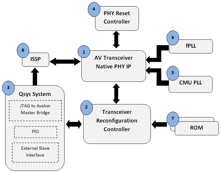
The design example consists of the following modules. The numbers refer to the position of the modules in the following figure. The system-level diagram shows how the different modules interact in the reconfiguration design example.
- Arria V GX Transceiver Native PHY IP
- Transceiver Reconfiguration Controller
- Qsys system
- PHY Reset Controller
- CMU PLL – Transceiver PLL
- Fractional PLL (fPLL) – Altera fPLL
- ROM containing the MIF for reconfiguration
- In-System Sources and Probes (ISSP)
The design example also contains a PRBS data generator and checker. The data generator generates a PRBS15 data pattern. The data checker verifies the PRBS15 data received.
Figure 1. System Diagram
- Creating the Qsys System
- Creating the Transceiver Native PHY IP
- Creating the Reconfiguration Controller
- Creating the CMU PLL Using an Arria V Transceiver PLL
- Creating a Fractional PLL (fPLL) using Altera PLL
- Creating the Transceiver PHY Reset Controller
- Creating a ROM that Contains the MIF for Reconfiguration
- Compiling the Design Example
- Creating In-System Sources and Probes (ISSP)
- Performing Reconfiguration with the System Console Tool
Related Information