Quartus® Prime Pro Edition User Guide: Block-Based Design
ID
683247
Date
8/30/2025
Public
1.1. Block-Based Design Terminology
1.2. Block-Based Design Overview
1.3. Design Methodologies Overview
1.4. Design Partitioning
1.5. Design Block Reuse Flows
1.6. Incremental Block-Based Compilation Flow
1.7. Setting-Up Team-Based Designs
1.8. Bottom-Up Design Considerations
1.9. Debugging Block-Based Designs with the Signal Tap Logic Analyzer
1.10. Block-Based Design Flows Revision History
3.1. Preserving the Device Resources
3.2. Fixing the Safety Partitions to Logic Lock Regions
3.3. Exporting and Importing Safety Logic Partitions
3.4. I/O Banks in Safety Partitions
3.5. Safety Region Verification Tool
3.6. Implementing Partitions for the Safety Separation Design Flow Revision History
3.4.1. Preserving GPIO IP and the I/Os in I/O Banks in Safety Partitions
3.4.2. Preserving IOPLL IP in I/O Banks in Safety Partitions
3.4.3. Preserving I/Os (other than GPIO IP I/Os) in I/O Banks in Safety Partitions
3.4.4. Verifying the Preserved I/Os in the Safety Partition
3.4.5. HSIO Bank 3A in a Safety Partition
1.5.2.2. Step 2: Developer: Define a Logic Lock Region
To reserve core resources in a Consumer project for the reserved core partition, the Developer defines a fixed size and location, core-only, reserved Logic Lock region with a defined routing region. The Consumer uses this same region in their project for core development. This region can contain only core logic.
Ensure that the reserved placement region is large enough to contain all core logic that the Consumer plans to develop. For projects with multiple core partitions, constrain each partition in a non-overlapping Logic Lock routing region.
Note: When reusing the root partition across different devices within the same family, you can only reuse the Synthesized snapshot, and you must ensure that any Fitter constraints (such as Logic Lock regions) from the Developer project do not conflict with constraints in the Consumer project.
Follow these steps to define a Logic Lock region for core development in the Developer project:
- Right-click the design instance in the Project Navigator and click Logic Lock Region > Create New Logic Lock Region. The region appears in the Logic Lock Regions Window. You can also verify the region in the Chip Planner (Locate Node > Locate in Chip Planner).
- Specify the placement region co-ordinates in the Origin column.
- Enable the Reserved and Core-Only options.
- For Size/State, select Fixed/Locked.
- Click the Routing Region cell. The Logic Lock Routing Region Settings dialog box appears.
Figure 14. Logic Lock Regions Window
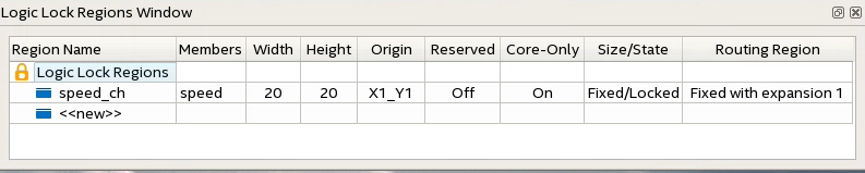
- Specify Fixed with expansion with Expansion Length of 1 for the Routing Type. For this flow you can select any value other than Unconstrained
- Click OK.
- Click File > Save Project.