1.3. Debugging the bit_bang_uart Project
This section demonstrates debugging techniques with the bit_bang_uart project. To start debugging bit_bang_uart, perform the following steps:
- In the Project Explorer view of the Nios II SBT for Eclipse, right click the bit_bang_uart, and select Nios II -> BSP Editor. Ensure the stdin, stdout and stderr are set to uart1.
- Open a Tera Term terminal and configure the connection to serial.
- In the Tera Term, on the setup menu, click serial port.
- Configure the serial port settings as shown in Debug Configuration Project figure.
- Click the New launch configuration button
 to create a new debug configuration. To name the debug configuration, in the Name box type neek_uart, and click Apply. Refer to the "Debug Configuration Project Tab" figure.
Figure 5. Debug Configuration Project Tab
to create a new debug configuration. To name the debug configuration, in the Name box type neek_uart, and click Apply. Refer to the "Debug Configuration Project Tab" figure.
Figure 5. Debug Configuration Project Tab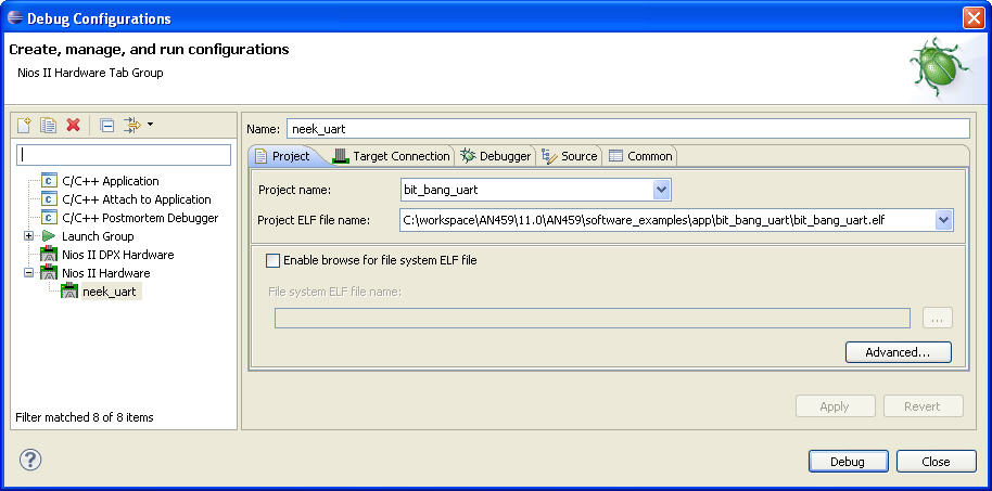
- On the Project tab, set Project name to bit_bang_uart, and set ELF file name to the path name of the application project’s Executable and Linking Format File (.elf).
- Verify that none of the tabs contains a red “x”, indicating an error. If any do, select that tab, and fill in the required data necessary to resolve the error as indicated by the tool's messages. For example, if more than one USB-Blaster cable is connected to your development host computer, the Target Connection tab has a red “x“. In this case, you must select the appropriate cable under Processors to resolve the error.
Note: If the message at the top of the dialog box says Actual system ID not found at target base address, on the Target Connection tab, click Refresh Connections. You might need to click Refresh Connections several times to establish a connection.Note: If the message at the top of the dialog box says System timestamp mismatch, on the Target connection tab, check on the Ignore mismatched system timestamp selection under the System ID checks.
- Click the Target Connection tab, see the Debug Configuration Target Connection Tab figure below. The message at the top of the dialog box says The expected Stdout device name does not match the selected target byte stream device name. This message is expected, because in the Connections panel, under Byte Stream Devices, the listed device is jtag_uart, while the stdout device used by the bit_bang_uart application is uart1. You use Tera Term to send and receive serial I/O. Tera Term is required because the Nios II SBT for Eclipse does not support the use of a UART as a byte stream device.
Figure 6. Debug Configuration Target Connection Tab
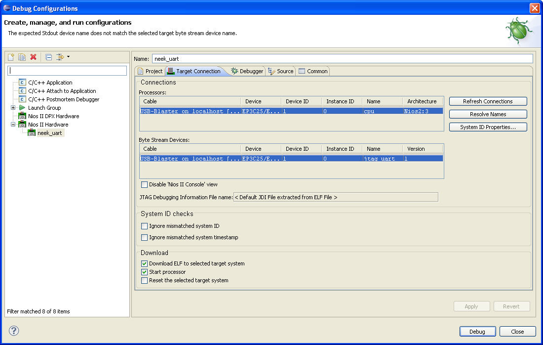
The jtag_uart byte stream device is used to receive Altera logging messages, as described in Debugging with the Altera Logging Functions section.
For additional information about setting up a debug configuration for Nios II SBT projects, refer to "Run Configurations" section in the "Getting Started with the Graphical User Interface" chapter of the Nios II Software Developer's Handbook.
- Click Debug.
- If Eclipse prompts you to switch to the Nios II Debug perspective, click Yes.
Note: Depending on how the Eclipse preferences are configured, Eclipse might automatically switch to the Nios II Debug perspective.
- Select the Nios II Console view.
- On the Window menu, choose to Show View and select Memory to open the Memory view.
- If the Memory view appears in the lower left corner, sharing a tabbed area with the Console view, drag the memory tab to the upper right corner of the perspective. This arrangement allows you to view the Console and Memory views simultaneously.
- Click the Add Memory Monitor button
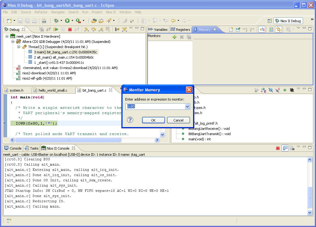
 in the Memory view, as shown in the Specifying Memory Address to Monitor figure below. This action opens a Monitor Memory dialog box in which you can type the memory address that you want to monitor.
 - Enter the UART peripheral's register base address, as shown in the Specifying Memory Address to Monitor figure below (0x80 for the uart1 peripheral in the design example accompanying this application note).
- Click OK.
- In the Memory view, right-click any cell under the column labeled 0 – 3, and click Format. Set Column Size to 1 unit per column.
- Click OK
Figure 7. Specifying Memory Address to Monitor
- Use the Step Over button
 to advance the program execution over the IOWR() macro. This macro transmit an asterisk to Tera Term by writing directly to the UART's transmit register as shown in the Asterisk Transmitted from Memory-Mapped Register figure.
 If you do not see an asterisk in Tera Term, verify your hardware cable is properly connected and your UART peripheral base address matches the one in your hardware design.
Figure 8. Asterisk Transmitted from Memory-Mapped Register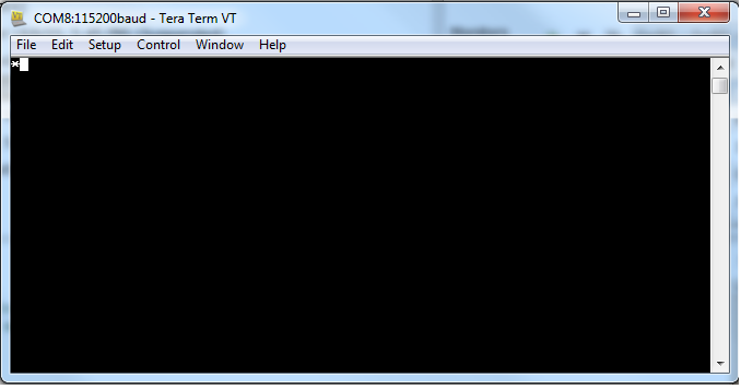
The red numbers in the Memory view indicate which memory values changed during the last “step over” operation. This change helps you verify that a new peripheral is functioning correctly. The 2A in the Memory view is the hexadecimal value for the asterisk character (*), as shown in the Transmit Asterisk figure below.
Figure 9. Transmit Asterisk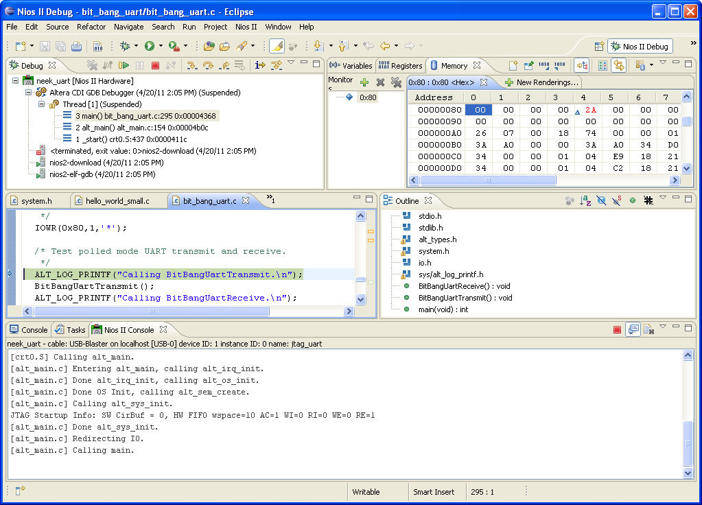
- To show the Memory view in ASCII rather than hexadecimal, click the New Renderings tab. Refer to the "Adding an ASCII Rendering to the Memory View" figure below. In the New Renderings tab, select ASCII and click Add Rendering(s).
The 2A in the Memory view changes to an asterisk.
Figure 10. Adding an ASCII Rendering to the Memory View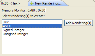
- You can transmit characters over the UART by directly changing memory values in the Memory view as follows:
- In the ASCII rendering, type an h in the cell currently occupied by the asterisk in the Memory view. This cell represents the transmit register.
- Press Enter.
- Type an i in the same cell in the Memory view.
- Press Enter.
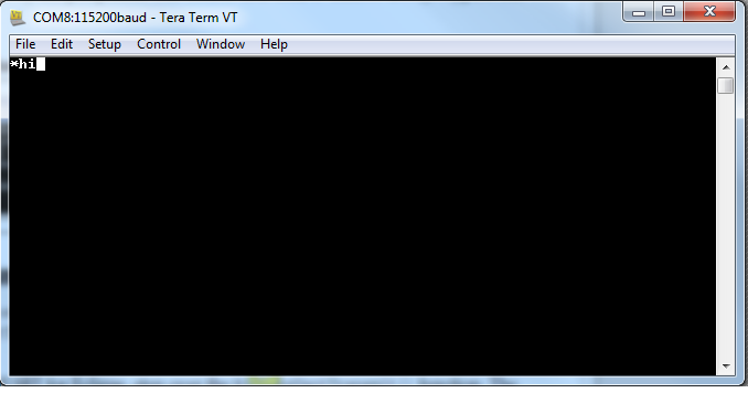
The word hi appears in Tera Term, as shown in the "Characters Transmitted by manipulating UART Register" figure below.
The peripheral memory-mapped registers bypass the cache. Therefore, the status register value displayed in the Memory view reflects any changes to the status register made by the peripheral. The IOWR() and IORD() macros always bypass the cache.
Figure 11. Characters Transmitted by manipulating UART Register