Visible to Intel only — GUID: GUID-7C48E698-70D5-48E6-B7EB-884C8313DE63
Getting Help and Support
Introducing the Intel® Integrated Performance Primitives for Intel® Architecture
Notational Conventions
Related Products
Getting Started with Intel® Integrated Performance Primitives
Intel® Integrated Performance Primitives Theory of Operation
Linking Your Application with Intel® Integrated Performance Primitives
Using Intel® Integrated Performance Primitives Platform-Aware Functions
Using Intel® Integrated Performance Primitives Threading Layer (TL) Functions
Using Custom Library Tool for Intel® Integrated Performance Primitives
Using Integration Wrappers for Intel® Integrated Performance Primitives
Programming Considerations
Programming with Intel® Integrated Performance Primitives in the Microsoft* Visual Studio* IDE
Appendix: Performance Test Tool Command-Line Options
Appendix: Intel(R) IPP Threading and OpenMP* Support
Intel® IPP API Reference
Notices and Disclaimers
Intel® Integrated Performance Primitives Concepts
Support Functions
Vector Initialization Functions
Essential Functions
Filtering Functions
Transform Functions
Fixed-Accuracy Arithmetic Functions
Long Term Evolution (LTE) Wireless Support Functions
Data Compression Functions
String Functions
Appendix A: Handling of Special Cases
Appendix B: Removed Functions for Signal Processing
Bibliography for Signal Processing
Glossary
SortAscend, SortDescend
SortIndexAscend, SortIndexDescend
SortRadixGetBufferSize
SortRadixAscend, SortRadixDescend
SortRadixIndexGetBufferSize
SortRadixIndexAscend, SortRadixIndexDescend
TopKGetBufferSize
TopKInit
TopK
SwapBytes
Convert
Conj
ConjFlip
Magnitude
Phase
PowerSpectr
Real
Imag
RealToCplx
CplxToReal
Threshold
Threshold_LT, Threshold_GT
Threshold_LTAbs, Threshold_GTAbs
Threshold_LTVal, Threshold_LTAbsVal, Threshold_GTVal, Threshold_LTValGTVal
Threshold_LTInv
CartToPolar
PolarToCart
MaxOrder
Flip
FindNearestOne
FindNearest
Special Parameters
Adler32
CRC32, CRC32C
DeflateLZ77
DeflateLZ77Fast
DeflateLZ77Fastest
DeflateLZ77FastestGenHeader
DeflateLZ77FastestGenHuffTable
DeflateLZ77FastestGetStat
DeflateLZ77FastestPrecompHeader
DeflateLZ77Slow
DeflateDictionarySet
DeflateUpdate Hash
DeflateHuff
InflateBuildHuffTable
Inflate
EncodeRLEInit_BZ2
RLEGetSize_BZ2
EncodeRLE_BZ2
EncodeRLEFlush_BZ2
RLEGetInUseTable
DecodeRLEStateInit_BZ2
DecodeRLEState_BZ2
DecodeRLEStateFlush_BZ2
EncodeZ1Z2_BZ2
DecodeZ1Z2_BZ2
ReduceDictionary
ExpandDictionary
CRC32_BZ2
EncodeHuffGetSize_BZ2
EncodeHuffInit_BZ2
PackHuffContext_BZ2
EncodeHuff_BZ2
DecodeHuffGetSize_BZ2
DecodeHuffInit_BZ2
UnpackHuffContext_BZ2
DecodeHuff_BZ2
DecodeBlockGetSize_BZ2
DecodeBlock_BZ2
EncodeZfpGetStateSize
EncodeZfpInit, EncodeZfpInitLong
EncodeZfpSet
EncodeZfpSetAccuracy
EncodeZfp444
EncodeZfpGetCompressedBitSize
EncodeZfpFlush
EncodeZfpGetCompressedSize, EncodeZfpGetCompressedSizeLong
DecodeZfpGetStateSize
DecodeZfpInit, DecodeZfpInitLong
DecodeZfpSet
DecodeZfpSetAccuracy
DecodeZfp444
DecodeZfpGetCompressedSize, DecodeZfpGetCompressedSizeLong
Intel® Integrated Performance Primitives Concepts
Support Functions
Image Data Exchange and Initialization Functions
Image Arithmetic and Logical Operations
Image Color Conversion
Threshold and Compare Operations
Morphological Operations
Filtering Functions
Image Linear Transforms
Image Statistics Functions
Image Geometry Transforms
Miscellaneous Image Transforms
Wavelet Transforms
Computer Vision
3D Data Processing Functions
Appendix A: Handling of Special Cases
Appendix B: Interpolation in Image Geometric Transform Functions
Appendix C: Removed Functions for Image and Video Processing
Bibliography for Image Processing
Glossary
RGBToYUV
YUVToRGB
RGBToYUV422
YUV422ToRGB
RGBToYUV420
YUV420ToRGB
BGRToYUV420
YUV420ToBGR
YUV422v210ToRGB, YUV422v210ToBGR
YUV422v210ToGray
RGBToYCbCr
YCbCrToRGB
YCbCrToBGR
YCbCrToBGR_709CSC
RGBToYCbCr422
YCbCr422ToRGB
RGBToYCrCb422
YCrCb422ToRGB, YCrCb422ToBGR
BGRToYCbCr422
YCbCr422ToBGR
YCbCr422ToGray
RGBToCbYCr422, RGBToCbYCr422Gamma
CbYCr422ToRGB
BGRToCbYCr422
BGRToCbYCr422_709HDTV
CbYCr422ToBGR
CbYCr422ToBGR_709HDTV
RGBToYCbCr420
YCbCr420ToRGB, YCbCr420ToBGR
RGBToYCrCb420
YCrCb420ToRGB, YCrCb420ToBGR
BGRToYCbCr420
BGRToYCbCr420_709CSC
BGRToYCbCr420_709HDTV
BGRToYCrCb420_709CSC
YCbCr420ToBGR
YCbCr420ToBGR_709CSC
YCbCr420ToBGR_709HDTV
BGRToYCrCb420
BGRToYCbCr411
YCbCr411ToBGR
RGBToXYZ
XYZToRGB
RGBToLUV, BGRToLUV
LUVToRGB, LUVToBGR
BGRToLab, RGBToLab
LabToBGR, LabToRGB
RGBToYCC
YCCToRGB
RGBToHLS
HLSToRGB
BGRToHLS
HLSToBGR
RGBToHSV
HSVToRGB
RGBToYCoCg
YCoCgToRGB
BGRToYCoCg
SBGRToYCoCg
YCoCgToBGR
YCoCgToSBGR
BGRToYCoCg_Rev
SBGRToYCoCg_Rev
YCoCgToBGR_Rev
YCoCgToSBGR_Rev
YCbCr422
YCbCr422ToYCrCb422
YCbCr422ToCbYCr422
YCbCr422ToYCbCr420
YCbCr422To420_Interlace
YCbCr422ToYCrCb420
YCbCr422ToYCbCr411
YCrCb422ToYCbCr422
YCrCb422ToYCbCr420
YCrCb422ToYCbCr411
CbYCr422ToYCbCr422
CbYCr422ToYCbCr420
CbYCr422ToYCbCr420_Interlace
CbYCr422ToYCrCb420
CbYCr422ToYCbCr411
YCbCr420
YCbCr420ToYCbCr422
YCbCr420ToYCbCr422_Filter
YCbCr420To422_Interlace
YCbCr420ToCbYCr422
YCbCr420ToCbYCr422_Interlace
YCbCr420ToYCrCb420
YCbCr420ToYCrCb420_Filter
YCbCr420ToYCbCr411
YCrCb420ToYCbCr422
YCrCb420ToYCbCr422_Filter
YCrCb420ToCbYCr422
YCrCb420ToYCbCr420
YCrCb420ToYCbCr411
YCbCr411
YCbCr411ToYCbCr422
YCbCr411ToYCrCb422
YCbCr411ToYCbCr420, YCbCr411To420
YCbCr411ToYCrCb420
Dilate3x3
Dilate
DilateBorder
DilateGetBufferSize
DilateGetSpecSize
DilateInit
Erode3x3
Erode
ErodeBorder
ErodeGetBufferSize
ErodeGetSpecSize
ErodeInit
GrayDilateBorder
GrayErodeBorder
MorphAdvInit
MorphAdvGetSize
MorphGetBufferSize
MorphGetSpecSize
MorphInit
MorphologyBorderGetSize
MorphologyBorderInit
MorphBlackhat
MorphBlackhatBorder
MorphClose
MorphCloseBorder
MorphGradient
MorphGradientBorder
MorphOpen
MorphOpenBorder
MorphTophat
MorphTophatBorder
MorphGrayInit
MorphGrayGetSize
MorphReconstructGetBufferSize
MorphReconstructDilate
MorphReconstructErode
MorphSetMode
Borders in Neighborhood Operations
User-defined Border Types
Constant Border
Replicated Border
Mirrored Border
Mirrored Border with Replication
Border in Memory
Mixed Borders
See Also
Filters with Borders
Median Filters
General Linear Filters
Separable Filters
Smoothing Filters
Wiener Filters
Convolution
Deconvolution
Fixed Filters
Deinterlacing Filters
FilterBilateral
FilterBilateralGetBufferSize
FilterBilateralInit
FilterBilateralBorderGetBufferSize
FilterBilateralBorderInit
FilterBilateralBorder
FilterBoxBorderGetBufferSize
FilterBoxBorder
FilterBox
FilterGaussianBorder
SumWindow
SumWindowGetBufferSize
SumWindowRow
SumWindowColumn
FilterMaxBorderGetBufferSize, FilterMinBorderGetBufferSize
FilterMaxBorder, FilterMinBorder
DecimateFilterRow, DecimateFilterColumn
FilterRowBorderPipelineGetBufferSize, FilterRowBorderPipelineGetBufferSize_Low
FilterRowBorderPipeline, FilterRowBorderPipeline_Low
FilterColumnPipelineGetBufferSize, FilterColumnPipelineGetBufferSize_Low
FilterColumnPipeline, FilterColumnPipeline_Low
FilterSeparable
FilterSeparableGetBufferSize
FilterSeparableGetSpecSize
FilterSeparableInit
FilterGaussianGetBufferSize
FilterGaussianGetSpecSize
FilterGaussianInit
FilterGaussian
FilterHipassBorderGetBufferSize
FilterHipassBorder
FilterLaplaceBorderGetBufferSize
FilterLaplaceBorder
FilterLaplacianGetBufferSize
FilterLaplacianBorder
FilterLowpassGetBufferSize
FilterLowpassBorder
FilterPrewittHorizBorderGetBufferSize
FilterPrewittHorizBorder
FilterPrewittVertBorderGetBufferSize
FilterPrewittVertBorder
FilterRobertsUpBorderGetBufferSize
FilterRobertsUpBorder
FilterRobertsDownBorderGetBufferSize
FilterRobertsDownBorder
FilterScharrHorizMaskBorderGetBufferSize
FilterScharrHorizMaskBorder
FilterScharrVertMaskBorderGetBufferSize
FilterScharrVertMaskBorder
FilterSharpenBorderGetBufferSize
FilterSharpenBorder
FilterSobelGetBufferSize
FilterSobelInit
FilterSobel
FilterSobelHorizBorderGetBufferSize
FilterSobelHorizBorder
FilterSobelHorizSecondBorderGetBufferSize
FilterSobelHorizSecondBorder
FilterSobelVertBorderGetBufferSize
FilterSobelVertBorder
FilterSobelVertSecondBorderGetBufferSize
FilterSobelNegVertBorderGetBufferSize
FilterSobelNegVertBorder
FilterSobelVertSecondBorder
FilterSobelCrossGetBufferSize
FilterSobelCrossBorder
GenSobelKernel
Sum
Integral
SqrIntegral
TiltedIntegral
TiltedSqrIntegral
Mean
Mean_StdDev
RectStdDev
TiltedRectStdDev
HistogramGetBufferSize
HistogramGetLevels
HistogramInit, HistogramUniformInit
Histogram
CountInRange
BlockMinMax
Min
MinIndx
Max
MaxIndx
MinMax
MinMaxIndx
MaxEvery
MinEvery
FindPeaks3x3GetBufferSize
FindPeaks3x3
Image Moments
Image Norms
Image Quality Index
Image Proximity Measures
Using Intel® IPP Resize Functions with Prior Initialization
ResizeGetSize
ResizeGetBufferSize
ResizeGetBorderSize
ResizeGetSrcOffset
ResizeGetSrcRoi
ResizeSetMode
ResizeNearestInit
ResizeNearest
ResizeLinearInit
ResizeLinear
ResizeCubicInit
ResizeCubic
ResizeLanczosInit
ResizeLanczos
ResizeSuperShiftInit
ResizeSuperInit
ResizeSuper
ResizeAntialiasingLinearInit
ResizeAntialiasingCubicInit
ResizeAntialiasingLanczosInit
ResizeAntialiasing
ResizeFilterGetSize
ResizeFilterInit
ResizeFilter
ResizeYUV420GetSize
ResizeYUV420GetSrcRoi
ResizeYUV420LanczosInit
ResizeYUV420SuperInit
ResizeYUV420GetBorderSize
ResizeYUV420GetSrcOffset
ResizeYUV420GetBufferSize
ResizeYUV420Lanczos
ResizeYUV420Super
ResizeYUV422GetSize
ResizeYUV422GetBorderSize
ResizeYUV422GetSrcOffset
ResizeYUV422GetBufSize
ResizeYUV422GetSrcRoi
ResizeYUV422NearestInit
ResizeYUV422LinearInit
ResizeYUV422Nearest
ResizeYUV422Linear
Using Intel® IPP Warp Affine Functions with Prior Initialization
Edge Smoothing
GetAffineQuad
GetAffineBound
GetAffineSrcRoi
GetAffineTransform
GetRotateTransform
GetRotateShift
WarpAffineGetSize
WarpQuadGetSize
WarpGetBufferSize
WarpAffineNearestInit
WarpQuadNearestInit
WarpAffineNearest
WarpAffineLinearInit
WarpQuadLinearInit
WarpAffineLinear
WarpAffineCubicInit
WarpQuadCubicInit
WarpAffineCubic
GetPerspectiveQuad
GetPerspectiveBound
GetPerspectiveTransform
WarpGetRectInfinite
WarpPerspectiveGetSize
WarpPerspectiveNearestInit
WarpPerspectiveNearest
WarpPerspectiveLinearInit
WarpPerspectiveLinear
WarpPerspectiveCubicInit
WarpPerspectiveCubic
Visible to Intel only — GUID: GUID-7C48E698-70D5-48E6-B7EB-884C8313DE63
User-defined Border Types
Some of the Intel® IPP image processing functions operate on user-defined border types. It means that the values of border pixels are assigned in accordance with the borderType (or border) and borderValue parameters.
Intel® IPP supports the following border types:
- Constant border
- Replicated border
- Mirrored border
- Mirrored border with replication
- Border in memory
- Mixed borders
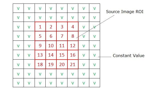
Constant Border
This type of border corresponds to the ippBorderConst value in the IppiBorderType enumerator. When using a constant border, values for all border pixels are set to the constant value that you specify in the borderValue parameter. In the figure below, this constant value is marked as V. Squares marked in red correspond to pixels copied from the source image ROI.
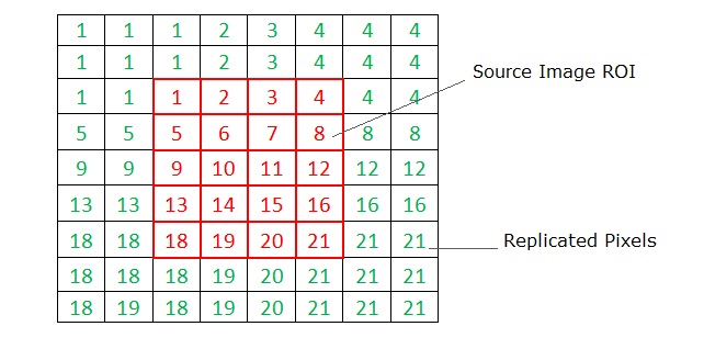
Replicated Border
This type of border corresponds to the ippBorderRepl value in the IppiBorderType enumerator. When using a replicated border, values for border pixels are obtained from the source image boundary pixels, as shown in the figure below. Squares marked in red correspond to pixels copied from the source image ROI. Squares with green values correspond to border pixels, which are replicated from the boundary pixels of the source image.
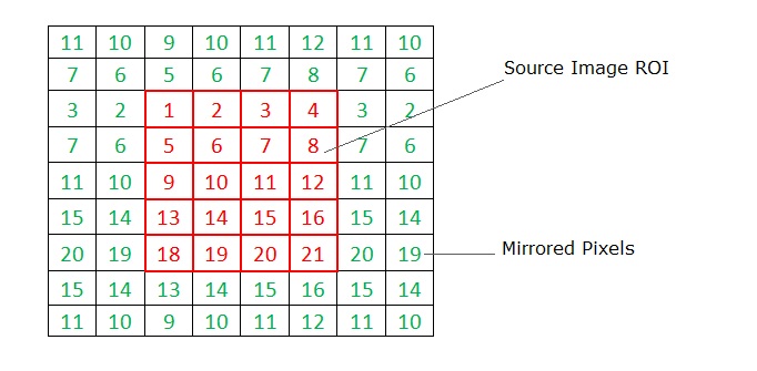
Mirrored Border
This type of border corresponds to the ippBorderMirror value in the IppiBorderType enumerator. When using a mirrored border, values for border pixels are obtained from the source image boundary pixels, as shown in the figure below. Squares marked in red correspond to pixels copied from the source image ROI. Squares with green values correspond to border pixels, which are mirrored from the source image pixels.
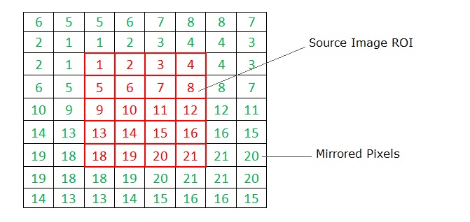
Mirrored Border with Replication
This type of border corresponds to the ippBorderMirrorR value in the IppiBorderType enumerator. When using a mirrored border with replication, values for border pixels are obtained from the source image boundary pixels, as shown in the figure below. Squares marked in red correspond to pixels copied from the source image ROI. Squares with green values correspond to border pixels, which are mirrored from the source image pixels. The difference of this border type from the mirrored border is that the anchor cell value is replicated to the border pixels.
Border in Memory
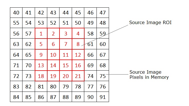
This type of border corresponds to the ippBorderInMem value and its flags combinations in the IppiBorderType enumerator. Use this border type if the ROI does not cover internal border pixels of the source image. In this case, values for border pixels are obtained from the source image pixels in memory. In the figure below, squares marked in red correspond to pixels copied from the source image ROI. Squares with black values correspond to source image pixels in memory.
Several Intel IPP filters operate in two or more stages. For example, the ippiMorphOpenBorder function performs filtering by applying the Erode and Dilate filters sequentially. You should note the following when setting borders for multistage filters:
- If you set the ippBorderInMem value or its flags combinations, the function tries to access pixels outside of image borders to get border pixels for each filtering stage. For example, the ippiMorphOpenBorder function uses two stages and with 5x5 mask will access floor(5/2)*2=4 pixels in each direction across the current ROI.
- If you set ippBorderFirstStageInMem, the function tries to access floor(5/2)=2 pixels outside of the image borders to get pixels for the first stage of filtering. The second filter will use one of the following border types to reconstruct image borders: ippBorderRepl, ippBorderConst, ippBorderMirror, or ippBorderMirrorR. To specify the border type for the second and next stages, use the bitwise OR operation between one of the listed above border types and ippBorderFirstStageInMem.
Mixed Borders
You can use mixed borders by using a bitwise OR operation between one of the ippBorderRepl, ippBorderConst, ippBorderMirror, or ippBorderMirrorR types and any of the following border types: ippBorderInMemTop, ippBorderInMemBottom, ippBorderInMemLeft, ippBorderInMemRight, or ippBorderFirstStageInMem. In this case, values for border pixels are obtained from the source image pixels in memory in the direction specified by the flag.
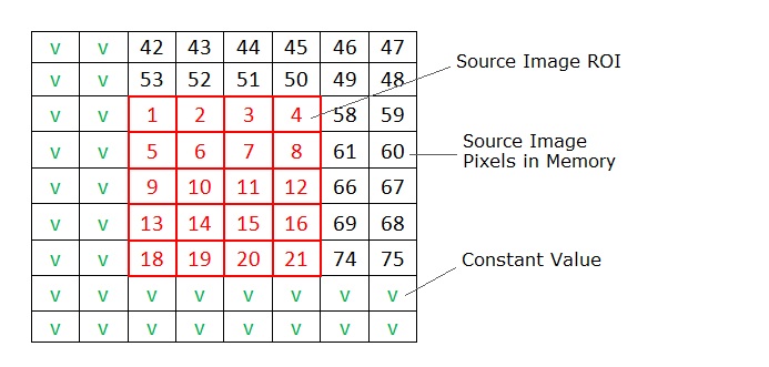
The figure below demonstrates the use of the ippBorderConst with the ippBorderInMemTop and ippBorderInMemRight borders. Squares marked in red correspond to pixels copied from the source image, that is the source image ROI. As you can see from the figure, top and right border pixels are obtained from the source image pixels in memory, while the rest of the border pixels are set to the constant value V.
NOTE:
The combination of ippBorderInMem and its flags always has priority over any other border flags or types. For example, if you specify ippBorderFirstStageInMem|ippBorderRepl|ippBorderInMemLeft, the left border will use InMem mode for each stage and other borders will use InMem for the first stage and replication for remaining stages.
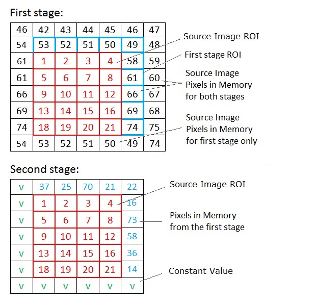
The figure below demonstrates the use of the ippBorderConst with the ippBorderInMemTop, ippBorderInMemRight, and ippBorderFirstStageInMem flags for two-stage filtering with one pixel border for both stages.
- First stage: squares marked in red correspond to pixels copied from the source image, which is the source image ROI, and squares marked in blue correspond to ROI assigned to the first stage filter. As you can see from the figure, the first stage enlarges ROI for top and right sides to consume more memory and provide valid pixels for the second stage memory border.
- Second stage: red squares and blue pixels correspond to resulting pixels from the first stage filter. Blue pixels lie outside of the ROI providing border values for the second stage in top and right directions. Left and bottom border pixels use the constant value V in accordance with the border flags combination.
Parent topic: Filtering Functions