5.1.2. OIF_Stressed PAM4 Link Simulation with the Advanced Link Analyzer
The schematic topology is as follows:
- Transmitter (No Equalization): Intel® Stratix® 10 E-Tile, IBIS-AMI Model
- TX Package: Intel® Stratix® 10 TX Package
- Transmitter Channel: OIF Stressed Link
- RX Package: Intel® Stratix® 10 RX Package
- Receiver (Adaptive): Intel® Stratix® 10 E-Tile, IBIS-AMI Model
Figure 31. OIF Stressed Link Simulation Results(a) = TX eye diagram, (b) = Channel eye diagram, (c) = RX CDR eye diagram
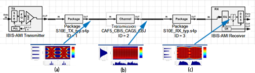
Figure 32. RX CDR BER EyeA BER contour of 1E-6 (passing the CEI-OIF-56G MR spec).
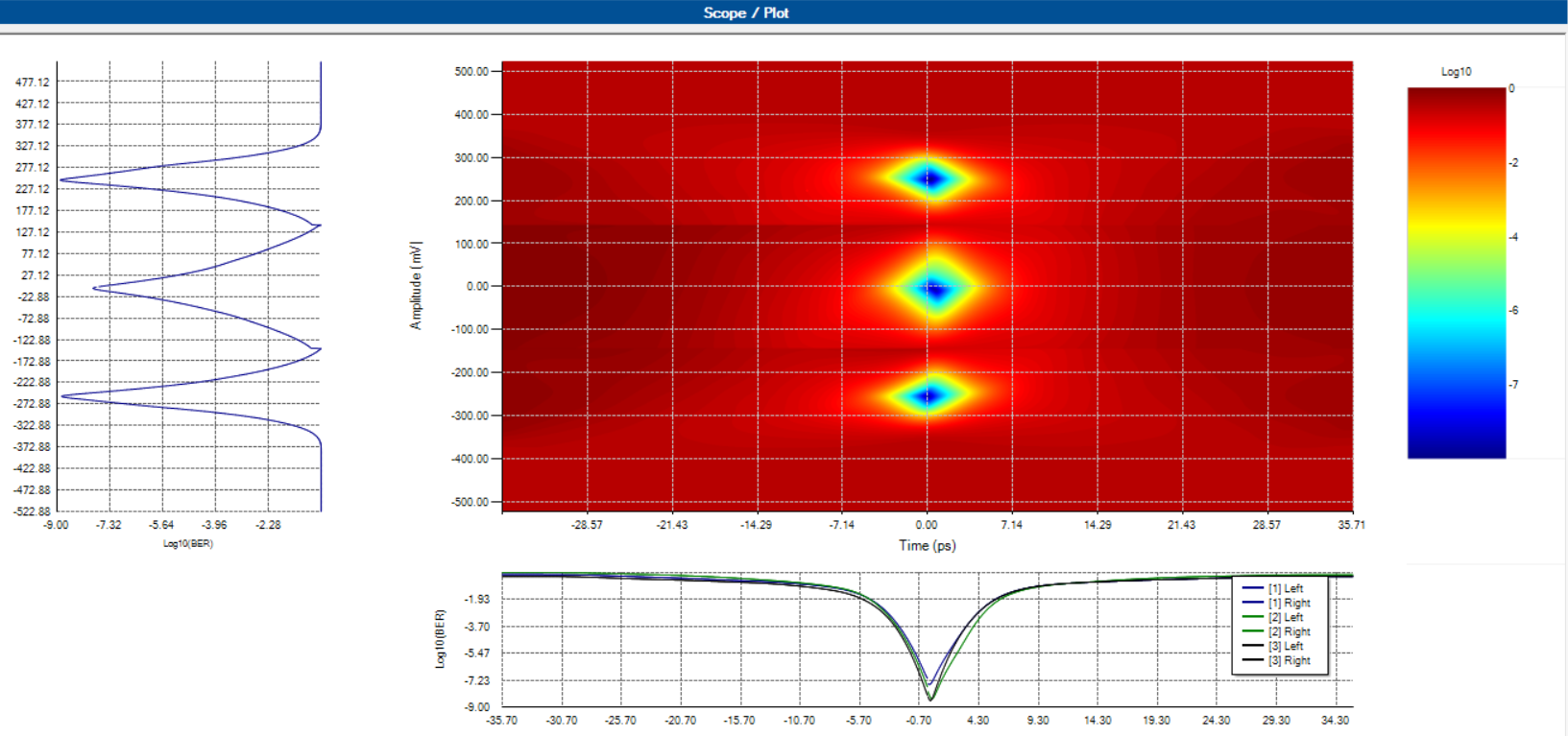
Figure 33. RX CDR FEC BER EyeA post FEC application, where the BER Eye has significantly improved to 1E-15.
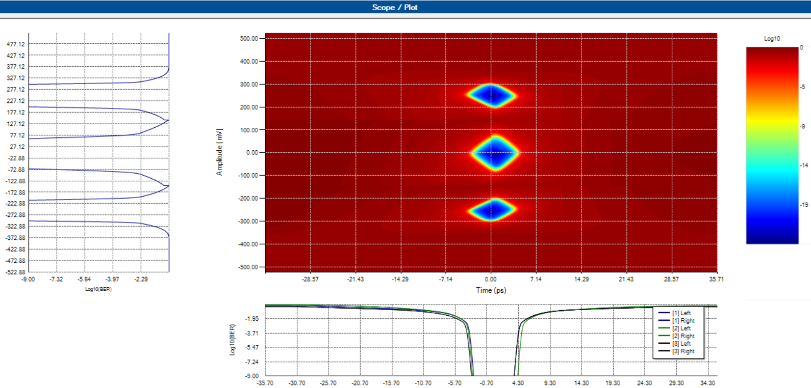
Advantage: Intel Advanced Link Analyzer can apply and provide RS FEC (544,514) projection to more accurately evaluate the channel performance. This is an unparalleled advantage compared to link simulation tools currently existing in the market.