2.1.4. Receiver Setting
A receiver receives waveforms from the channel and processes the waveforms through the receiver equalizer and clock and data recovery module.
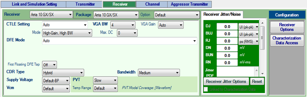
Intel® Advanced Link Analyzer provides the following settings and configurations for receivers:
Receiver
The following receiver types are supported:
- Stratix® V GX
- Arria® V GZ
- Stratix® V GT
- Arria® 10 GX/SX
- Arria® 10 GT
- Stratix® 10 L-tile (wrapper support)
- Stratix® 10 H-tile (wrapper support)
- Stratix® 10 E-tile (wrapper support)
- Stratix® 10 P-tile (wrapper support)
- Agilex™ 7 E-tile (wrapper support)
- Agilex™ 7 P-tile (wrapper support)
- Agilex™ 7 R-tile (wrapper support)
- Agilex™ 7 P-tile (wrapper support)
- Agilex™ 7 F-tile general-purpose transceiver block (wrapper support)
- Agilex™ 7 F-tile high-speed transceiver block (wrapper support)
- Agilex™ 5 (wrapper support)
- IBIS-AMI
- IBIS-AMI with Input Clock
- Custom
- Custom with Input Clock
- PCI Express* 8GT
- PCI Express* 16GT
- PCI Express* 32GT
Parameters or selections within the receiver setting are specific to the receiver type. For example, package model, available CDR (Clock and Data Recovery) type and bandwidth, available CTLE (Continuous Time Linear Equalizer) selections, DFE operation mode and settings, and additional receiver options, are set and shown when a new device is selected. When a new receiver is chosen, it is automatically inserted into the Link Designer, ready for connecting to other link components.
Package
Select the package type for a receiver device. For Intel products and PCI Express* 8GT receivers, the package models are included in the receiver models. For Custom devices, you can specify package models in the channel setting by inserting a “Package” channel component. When you select the Custom package type (for any transmitter device), the embedded package mode (if available) is disabled, and you can add a channel component (such as an S-parameter) with type Package in the Link Designer workspace. The Custom package model must be placed adjacent to the receiver module so it can be simulated and analyzed correctly. If you choose the Custom package type but do not add a channel component with Package type to the Link Designer workspace, the receiver is simulated without any package model. Selecting Package Designer from the Package pull-down menu opens the Receiver Package Designer for you to design or customize package models. Refer to the "Transmitter Package Designer User Interface" figure and description in Transmitter Setting for how to configure the package designer.
Intel® Advanced Link Analyzer comes with the following receiver package models:
- Stratix® V GX
- Arria® V GZ
- Stratix® V GT
-
Arria® 10 GX/SX
Options: Additional package models (shown in the following figure) are available for Arria® 10 devices. The package model is specified as its trace length inside the package. These models are chosen to cover the range of package trace lengths in Arria® 10 transceiver receivers.
- Default—The default package model is the same as the 14 mm option
- 14mm
- 16.5mm
- 20mm
- 24mm
Contact My Intel support if you want to know how to pair your design with the Arria® 10 package model options.
Figure 47. Arria® 10 Receiver Package Options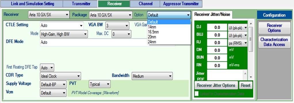
- Arria® 10 GT—Same options as Arria® 10 GX/SX
- Stratix® 10 L-tile/H-tile/E-tile (wrapper support)—Typical, Minimum, and Maximum package models are provided
- PCI Express* 8GT
- PCI Express* 16GT (place holder only; use custom package model for simulations)
- PCI Express* 32GT
CTLE Setting
Select or specify the CTLE (Continuous-Time Linear Equalizer) operation mode and model. Auto, Manual, and Off (if available) settings are supported.
- Intel device receivers:
- Stratix® V GX, Arria® V GZ, Stratix® V GT, Arria® 10 GX/SX and Arria® 10 GT CTLE models are embedded in Intel® Advanced Link Analyzer.
- Both Auto and Manual settings are supported.
- In Manual setting, EQ Bandwidth, AC Gain, and DC Gain menus are shown for user selection.
- In Auto setting, you select the EQ bandwidth and maximum CTLE DC gain level (if available) that you want to use.
- Intel® Advanced Link Analyzer uses Intel’s proprietary algorithm to find optimal CTLE setting in Auto setting.
Note: In IBIS-AMI wrapper mode, the CTLE Setting menu can contain parameter selections originated from the underlying IBIS-AMI models. Please refer to the user guide of the IBIS-AMI model for operating mode definition. - Custom receiver and PCI Express* 8GT/16GT/32GT receiver—You can select or input the CTLE gain (in dB) listed in the pull-down menu. The custom CTLE model can use the PCI Express* 8GT CTLE behavior model template and IEEE 802.3cd COM CTLE model template. Refer "Receiver Options" sections for further information.
VGA Bandwidth
The VGA Bandwidth selection is available when an Arria® 10 GX/SX/GT model is selected. The available VGA bandwidth settings are listed in the pull-down menu. The default setting is 4 (highest bandwidth).
VGA Gain
The VGA Gain selection is available when an Arria® 10 GX/SX/GT, Stratix® 10 L-tile, or Stratix® 10 H-tile model is selected. The available VGA gain settings are listed in the pull-down menu. If Auto (default setting) is selected, the VGA gain setting is determined by the receiver model.
DFE Mode
The DFE can operate in Auto mode, Manual mode, or be disabled.
- Intel receivers:
- Stratix® V GX, Arria® V GZ, Arria® 10 GX/SX and Arria® 10 GT models are supported in both Auto mode and Manual mode.
- In Auto mode, Intel® Advanced Link Analyzer finds the optimal DFE setting for the given link configuration.
- In Manual mode, you select and set each DFE tap level.
- For Arria® 10 GX/SX/GT, the floating DFE tap is no longer supported. To disable the floating DFE tap function, select Off in the First Floating DFE Tap pull-down menu.
- Custom receiver and PCI Express* receivers— Intel® Advanced Link Analyzer implements a generic behavior DFE model. You can customize the DFE model with the Receiver Options Window.
CDR Type and CDR Bandwidth
Select the type of Clock and Data Recovery (CDR) module used in the receiver. There are two options: Ideal Clock and supported CDR type. When you select the ideal clock option, the eye diagram is plotted using the ideal system clock. When you enable CDR, both ideal clocked and CDR retimed eye diagrams are shown.
- Intel Receivers— Stratix® V GX, Arria® V GZ, Stratix® V GT, Arria® 10 GX/SX and Arria® 10 GT, Cyclone® 10 GX Hybrid CDR models are supported. The CDR models and configurations are automatically set according to the data rate and CDR bandwidth setting. Consult Intel design guides for CDR bandwidth configurations. With Intel® devices supported by IBIS-AMI wrapper technology, CDR is modeled within the underlying receiver IBIS-AMI model. Refer to IBIS-AMI model's user guide for details.
- Custom receiver and PCI Express* 8GT/16GT/32GT receivers—A generic CDR, with bang-bang phase detector, is supported. The CDR bandwidth for the generic receiver is 18 MHz (low bandwidth), 26 MHz (medium bandwidth), and 34 MHz (high bandwidth).
Supply Voltage
For supported devices, you can choose the supply voltage. The Arria® 10 GX/SX/GT and Cyclone® 10 GX receiver model provides the following supply voltages:
- 0.95 V ( Arria® 10 GX/SX/GT and Cyclone® 10 GX)
- 1.03 V ( Arria® 10 GX/SX/GT and Cyclone® 10 GX)
- 1.12 V ( Arria® 10 GT)
Vcm
Vcm is the common voltage of the receiver input signal. Vcm options are only available when CTLE mode is QPI.
PVT
Select the process, voltage, and temperature (PVT) models for the selected receiver device. PVT model support varies depending on device type, device data availability, and model coverage. A message is shown on the Receiver tab page to indicate the PVT model coverage. Receiver PVT model coverage and conditions are shown in the following table.
| Receiver Type | Waveform PVT Model | Jitter/Noise PVT Model |
|---|---|---|
| Stratix® V GX | Typical | Process: Typical/Fast/Slow Voltage: Typical/High/Low Temperature: –40°C to 100°C |
| Arria® V GZ | Typical | Process: Typical/Fast/Slow Voltage: Typical/High/Low Temperature: –40°C to 100°C |
| Stratix® V GT | Typical | Process: Typical/Fast/Slow Voltage: Typical/High/Low Temperature: 0°C to 100°C |
| Arria® 10 GX/SX | Typical/Fast/Slow | Slow |
| Arria® 10 GT | Typical/Fast/Slow | Slow |
| Stratix® 10 L-tile/H-tile/E-tile/P-tile | Typical/Fast/Slow | Slow |
| Wrapper supported Intel IBIS-AMI model | Provide by IBIS-AMI model | Provide by IBIS-AMI model |
| Cyclone® 10 GX | Typical/Fast/Slow | Slow |
| IBIS-AMI | Provide by IBIS-AMI model | Provide by IBIS-AMI model |
| Custom | None | None |
| PCI Express* 8GT/16GT/32GT | None | None |
Temp Range
For Arria® 10, the device model have temperature range dependency. The temperature range is -40 °C to 100 °C for Industrial, 0 °C tp 105 °C for Extended, and -40 °C to 125 °C for Military. The default setting is Industrial temperature range. Refer to the device's data sheet for the supported temperature range; values in the datasheet take precedence over the values in this document.
Intel® Advanced Link Analyzer to Quartus® Prime Parameter Translation for Arria® 10 GX/SX/GT Receivers
The following table shows the mapping between the Intel® Advanced Link Analyzer’s Arria® 10 GX/SX/GT receiver model parameters and the Assignments Editor entries in the Quartus® Prime software. Unless otherwise noted, values translate directly between the two domains.
| Intel® Advanced Link Analyzer Name | Quartus® Prime Name |
|---|---|
| Receiver On-Chip- Termination | |
| Supply Voltage | Vccer/Vccet Power |
| CTLE Setting / Mode | Eq_bw_sel (Equalizer bandwidth Selection) If Receiver High Data Rate Mode Equalizer = 1
If Receiver High Data Rate Mode Equalizer = 0
|
| VGA BW | VGA_bandwidth_Select |
| CTLE Setting / Mode | Receiver High Data Rate Mode Equalizer If Receiver High Data Rate Mode Equalizer = 1
If Receiver High Data Rate Mode Equalizer = 0
|
| CTLE Setting
|
Refer to the Arria® 10 Transceiver PHY User Guide |
| AC Gain with CTLE Setting = Manual Mode = High Data Rate | Receiver High Data Rate Mode Equalizer AC Gain Control |
| AC Gain with CTLE Setting = Manual Mode = High Gain | Receiver High Gain Mode Equalizer AC Gain Control |
| DC Gain with CTLE Setting = Manual Mode = High Gain | Receiver High Gain Mode Equalizer DC Gain Control |
| VGA Gain | Receiver Variable Gain Amplifier Voltage Swing Select |
| DFE Mode | Receiver Decision Feedback Equalizer Mode |
| DFE Tap 1 | Receiver Decision Feedback Equalizer Fix Tap One Coefficient |
| DFE Tap 2 | Receiver Decision Feedback Equalizer Fix Tap Two Coefficient |
| DFE Tap 3 | Receiver Decision Feedback Equalizer Fix Tap Three Coefficient |
| DFE Tap 4 | Receiver Decision Feedback Equalizer Fix Tap Four Coefficient |
| DFE Tap 5 | Receiver Decision Feedback Equalizer Fix Tap Five Coefficient |
| DFE Tap 6 | Receiver Decision Feedback Equalizer Fix Tap Six Coefficient |
| DFE Tap 7 | Receiver Decision Feedback Equalizer Fix Tap Seven Coefficient |
| RX Impedance (R in Receiver Options / Termination) |
Receiver On-Chip- Termination |
| CDR Type Hybrid |
Arria® 10 Transceiver CMU PLL |
| CDR Bandwidth | Bandwidth in PLL Options |