A newer version of this document is available. Customers should click here to go to the newest version.
3.1.2. Small ROM Architecture
.To reduce memory usage (but increase LE usage) and increase output frequency, use the small ROM architecture.
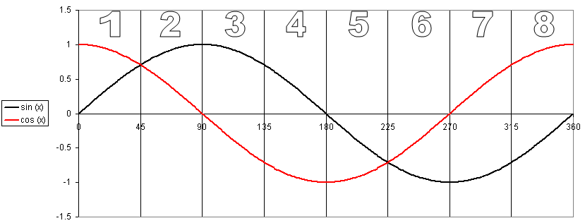
In a small ROM architecture, the device memory only stores 45 degrees of the sine and cosine waveforms. All other output values are derived from these values based on the position of the rotating phasor on the unit circle.
| Position in Unit Circle | Range for Phase x | sin(x) | cos(x) |
|---|---|---|---|
| 1 | 0 <= x < π/4 | sin(x) | cos(x) |
| 2 | π/4 <= x < π/2 | cos(π/2-x) | sin(π/2-x) |
| 3 | π/2 <= x < 3π/4 | cos(x-π/2) | -sin(x-π/2) |
| 4 | 3π/4 <= x < π | sin(π-x) | -cos(π-x) |
| 5 | π <= x < 5π/4 | -sin(x-π) | -cos(x-π) |
| 6 | 5π/4 <= x < 3π/2 | -cos(3π/2-x) | -sin(3π/2-x) |
| 7 | 3π/2 <= x < 7π/4 | -cos(x-3π/2) | sin(x-3π/2) |
| 8 | 7π/4 <= x < 2π | -sin(2π-x) | cos(2π-x) |
A small ROM implementation is more likely to have periodic value repetition, so the resulting waveform's SFDR is lower than that of the large ROM architecture. However, you can often mitigate this reduction in SFDR by using phase dithering.
Figure 9. Derivation of output Values
Related Information