Intel® Acceleration Stack User Guide: Intel® FPGA Programmable Acceleration Card N3000-N/2
ID
683362
Date
11/01/2021
Public
1. About this Document
2. System Requirements
3. Hardware Installation
4. Installing the OPAE Software
5. Identify the Intel® MAX® 10 BMC Version
6. Intel XL710 Driver Installation and Firmware Update
7. Updating the Retimer Firmware
8. OPAE Tools
9. Sample Test: Native Loopback
10. Configuring Ethernet Interfaces
11. Testing Network Loopback Using Data Plane Development Kit (DPDK)
12. Graceful Shutdown
13. Single Event Upset (SEU)
14. Document Revision History for Intel Acceleration Stack User Guide: Intel® FPGA PAC N3000-N/2
A. Troubleshooting
B. fpgabist Sample Output
3.1. Installing the Intel® FPGA PAC N3000-N/2
Complete these steps to install the Intel® FPGA PAC N3000-N/2:
- Power down the system.
- Plug the Intel® FPGA PAC N3000-N/2 into a PCIe x16 physical and x16 electrical slot on the motherboard.
- Connect the auxiliary power to the 12 V 6-pin connector using an applicable cable.
Note: Make sure the auxiliary power cable does not block airflow to the Intel® FPGA PAC N3000-N/2.
- Enable the following options in the BIOS:
- Intel VT-x (Intel Virtualization Technology for IA-32 and Intel 64 Processors)
- Intel VT-d (Intel Virtualization Technology for Directed I/O)
- For network testing, you can insert a loopback module into each QSFP28 port.
Note: ESD protection is required while handling the Intel® FPGA PAC N3000-N/2.Warning: Take caution when you are inserting and removing the cards into PCIe slots. The bottom side of the card has capacitors and resistors that can be knocked off if the cards scrapes against edges or corners of the slot in the chassis.Figure 3. Example of QSFP Non-optical ModulesThis is a 25 GbE QSFP setup.
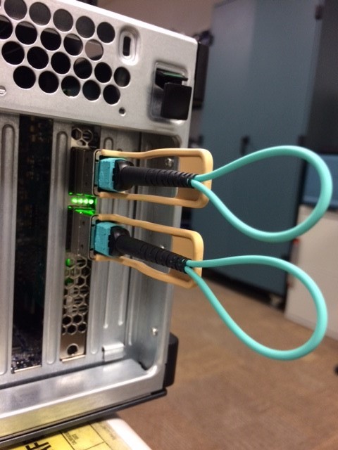
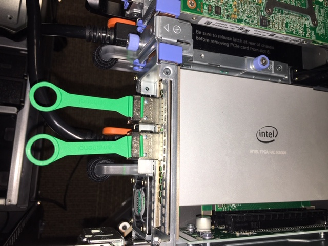 Figure 4. Example of QSFP Loopback Optical Modules
This figure shows the correct orientation of the QSFP module for optical loopback testing.
- Power on the system and observe the Ethernet status LEDs which are located between the QSFP connectors. The LED operation is described in the table below:
Table 1. LED Behavior LED Type Description Connectivity LED Green means link is up with link speed of 25G. Off means link is down. Activity LED Green blinking at 1 Hz means link activity present. Off means link is down or no activity. All LEDs blinking yellow It means either: - 12 V Auxiliary or PCIe edge supply voltage is below 10.46 V or
- FPGA core temperature reaches 100°C or
- Board temperature reaches 100°C
You should check the following:- Card insertion in PCIe slot.
- 12 V Auxiliary connection on the Intel® FPGA PAC N3000-N/2 and on the server motherboard.
- Fan setting for cooling air flow. Sufficient airflow is required whenever the Intel® FPGA PAC N3000-N/2 is powered on.
For details on the location of Connectivity and Activity LEDs, refer to the Intel® FPGA Programmable Acceleration Card N3000-N Data Sheet or Intel FPGA Programmable Acceleration Card N3000 Data Sheet.
Figure 5. Ethernet Status LEDs Power-On IndicationThis figure is an example of 25G configuration where both Ethernet links are UP with ongoing Ethernet activity.
- I/O Memory Management Unit (IOMMU) support is not enabled by default in CentOS Linux 7.0 distribution. IOMMU support is required for a virtual function (VF) to function properly when assigned to a virtual machine (VM).
- Edit the /etc/default/grub and add iommu=pt iommu=on default_hugepagesz=1G hugepagesz=1G hugepages=2 hugepagesz=2M hugepages=200 to the GRUB_CMDLINE_LINUX entry.
For example:
GRUB_CMDLINE_LINUX="crashkernel=auto rd.lvm.lv=centos/root rd.lvm.lv=centos/\
swap rhgb quiet pci=realloc intel_iommu=pt intel_iommu=on default_hugepagesz=1G hugepagesz=1G hugepages=2 hugepagesz=2M hugepages=200"
- GRUB reads its configuration either from /boot/grub2/grub.cfg file on traditional BIOS-based machines or from /boot/efi/EFI/redhat/grub.cfg file on UEFI machines. Depending on your system, execute one of the following instructions as root:
- For BIOS based machine:
# grub2-mkconfig -o /boot/grub2/grub.cfg
- For UEFI based machine:
# grub2-mkconfig -o /boot/efi/EFI/centos/grub.cfg
Generating grub configuration file ...
Found linux image: vmlinuz-4.19.106-rt45
Found initrd image: initramfs-4.19.106-rt45
 Found linux image: /boot/vmlinuz-0-
rescue-594cabaaf9a84c6ea0a5167c89ad916d Found initrd image: /boot/initramfs-0- rescue-594cabaaf9a84c6ea0a5167c89ad916d.img
- For BIOS based machine:
- Reboot your server to apply the new GRUB configuration file.
- To verify the GRUB update, run the following command:
$ cat /proc/cmdline
Sample output showing intel_iommu=on on the kernel command line.:BOOT_IMAGE=/vmlinuz-4.19.106-rt45 root=/dev/mapper/centos-root ro default_hugepagesz=1G hugepagesz=1G hugepages=2 hugepagesz=2M hugepages=200 nosoftlockup mce=ignore_ce audit=0 isolcpus=1-11,24-35,13-23,36-47 nohz_full=1-11,24-35,13-23,36-47 rcu_nocbs=1-11,24-35,13-23,36-47 pci=realloc intel_iommu=on iommu=pt enforcing=0 crashkernel=auto rd.lvm.lv=centos/root rd.lvm.lv=centos/swap rhgb quiet skew_tick=1
- Edit the /etc/default/grub and add iommu=pt iommu=on default_hugepagesz=1G hugepagesz=1G hugepages=2 hugepagesz=2M hugepages=200 to the GRUB_CMDLINE_LINUX entry.
- Set POSIX locale:
A locale is a set of environmental variables that defines the language, country, and character encoding settings for applications and shell session on a Linux system.
- Run the following command to check if LC_ALL is set to UTF-8:
$ locale
Sample output:
LANG=en_US.UTF-8
LC_CTYPE="en_US.UTF-8"
LC_NUMERIC="en_US.UTF-8"
LC_TIME="en_US.UTF-8"
LC_COLLATE="en_US.UTF-8"
LC_MONETARY="en_US.UTF-8"
LC_MESSAGES="en_US.UTF-8"
LC_PAPER="en_US.UTF-8"
LC_NAME="en_US.UTF-8"
LC_ADDRESS="en_US.UTF-8"
LC_TELEPHONE="en_US.UTF-8"
LC_MEASUREMENT="en_US.UTF-8"
LC_IDENTIFICATION="en_US.UTF-8"
LC_ALL=
- To set UTF-8 encoding, add the following in ~/.bash_profile:
export LC_ALL=en_US.UTF-8
export LANG=en_US.UTF-8
export LANGUAGE=en_US.UTF-8
- Restart the terminal.
- Run the following command to check if LC_ALL is set to UTF-8:
Note: If your server is set up with secure boot, the OPAE Remote Setup (RSU) command will not function. This RSU limitation is due to secure boot having the following limitations:
- Using kexec to start an unsigned kernel image.
- Hibernation and resume from hibernation.
- User-space access to physical memory and I/O ports.
- Module parameters that allow setting memory and I/O port addresses.
- Writing to MSRs through /dev/cpu/*/msr.
- Use of custom ACPI methods and tables.
- ACPI APEI error injection.