5.1. Cooling Requirements
Figure 7. Forward Flow Cooling Curve
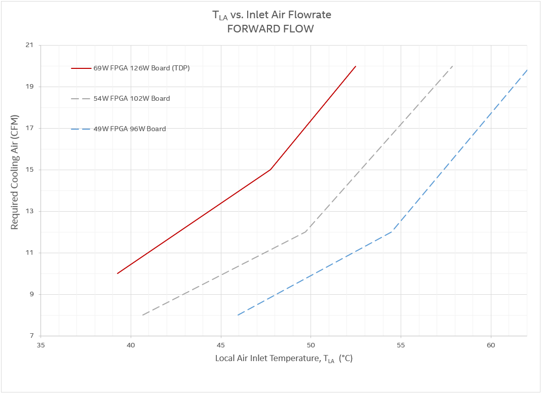
| FPGA Power < 49 W Board Power < 96 W |
FPGA Power < 54 W Board Power < 102 W |
FPGA Power < 69 W Board Power < 126 W (TDP) |
|||
|---|---|---|---|---|---|
| Maximum TLA (°C) | Air Flow (CFM) | Maximum TLA (°C) | Air Flow (CFM) | Maximum TLA (°C) | Air Flow (CFM) |
| 46 | 8 | 40.7 | 8 | 39.2 | 10 |
| 54.5 | 12 | 49.8 | 12 | 47.8 | 15 |
| 62 | 20 | 57.9 | 20 | 52.3 | 20 |
Figure 8. Reverse Flow Cooling Curve
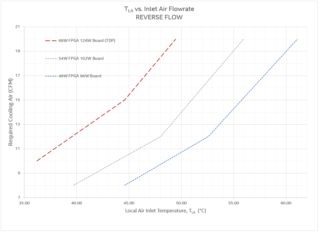
| FPGA Power < 49 W Board Power < 96 W |
FPGA Power < 54 W Board Power < 102 W |
FPGA Power < 69 W Board Power < 126 W (TDP) |
|||
|---|---|---|---|---|---|
| Maximum TLA (°C) | Air Flow (CFM) | Maximum TLA (°C) | Air Flow (CFM) | Maximum TLA (°C) | Air Flow (CFM) |
| 44.6 | 8 | 39.8 | 8 | 36.1 | 10 |
| 52.6 | 12 | 48 | 12 | 44.7 | 15 |
| 61 | 20 | 56 | 20 | 49.4 | 20 |
Note: TLA values shown in the tables and charts of this section are informational, and may represent conditions outside of the supported operating range.
Note: These flow curves are based on numerical analysis and should be used as a starting point for thermal design estimation. Thermal performance of host systems may vary. Therefore, you should perform in-system thermal validation.