4.1. Migration via Migration GUI for 1SG040HH2F3512VG-1SG065HH3F3512VG Devices
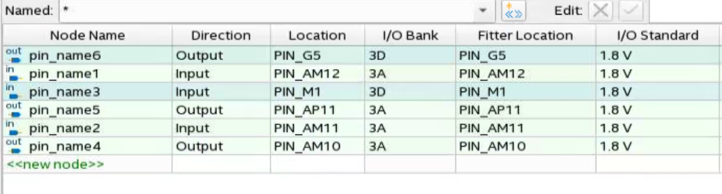
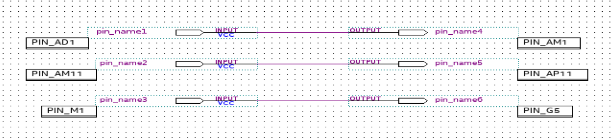
The designs used in this application note are basic designs to address the assignment issues. Figure 9 is the snapshot of the design with the pin assignments.
- To start the device migration (1SG040HH2F3512VG-1SG065HH3F3512VG), right click on the device tab in the Project Navigator window. This will navigate you to a pop-up window as shown in the Figure 10.
Figure 10. Device Page
- Instead of changing the device directly (which will allow the Intel® Quartus® Prime software to migrate to a new device by removing all the location assignments), select the Migration Devices tab located at the bottom right of Figure 10. When you select the Migration Devices tab, a window will pop up as shown in Figure 11.
Figure 11. Migration Devices
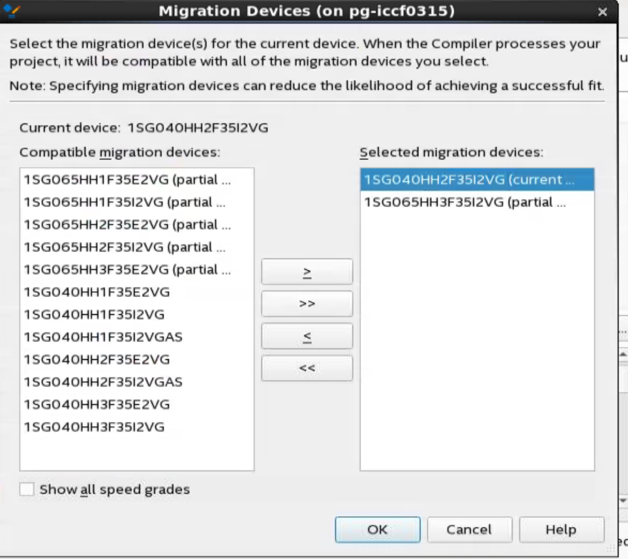
- In the Migration Devices dialog box, click on >, >>, <, and << to move the migration devices between the Compatible migration devices list and the Selected migration devices list.
A device name in the Selected migration devices list that is followed by the text (current device) indicates that the device is currently specified in the Available devices list in the Device dialog box.Compatible devices are listed in the Compatible migration devices list as partially or fully.Note: Partially migratable device list will be shown in the Intel® Quartus® Prime software version 20.2 onwards.
If you want the Intel® Quartus® Prime software to display all compatible migration devices in the Compatible migration devices list regardless of a migration device's speed grade, then turn on the Show All Speed Grades option. If you want the Intel® Quartus® Prime software to display only the Compatible migration devices that have the same speed grade as the target device in the Compatible migration devices list, then turn off the Show all speed grades option.
- After choosing the device for migration (1SG065HH3F3512VG), click OK and then you can check the assignment in the .qsf file too. If you do not specify at least one migration device in the Migration Devices dialog box, then the field displays 0 migration devices selected.
Figure 12. Set Global Assignment

- After specifying the device to use as a migration device, compile the design. However, the device migration may cause additional constraints. Compilation may fail due to the additional constraints, and shows the error message as shown in Figure 13. The errors appear because the devices are partially migratable. These errors prompt you to check the pin assignment in the Pin Planner as shown in Figure 14.
Figure 13. Error Message
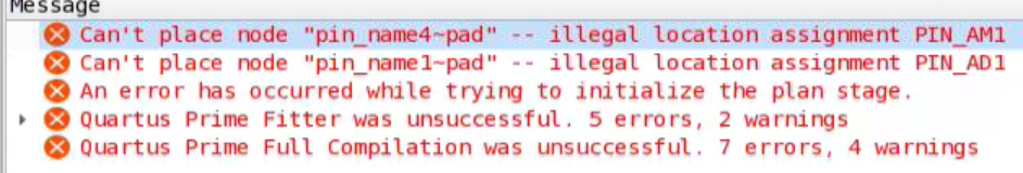 Figure 14. Pin Planner
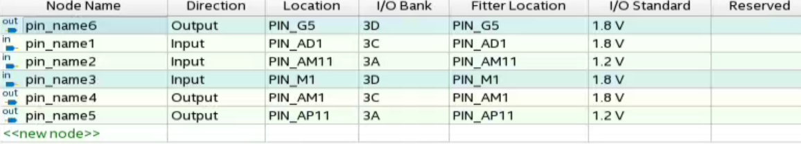
- For the non-migratable I/O pins, leave them as NC. You can set the unused I/O pins as input tri-state in the Intel® Quartus® Prime software.
Go to the Device from the Project Navigator window and click on the Devices and Pin Options as shown in Figure 15. In the Device and Pin Options window, under the Reserve all unused pins drop-down list, select As input tri-stated.
Figure 15. Devices PageFigure 16. Devices and Pin Options - Remove the location assignment of the non-migratable pins as shown in Figure 17 and compile the design.
Figure 17. Location Assignment
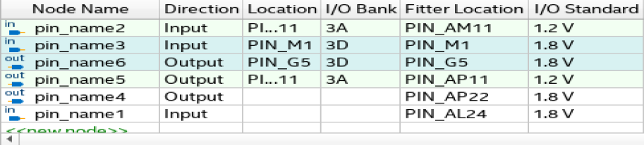 Figure 18. Design Compilation
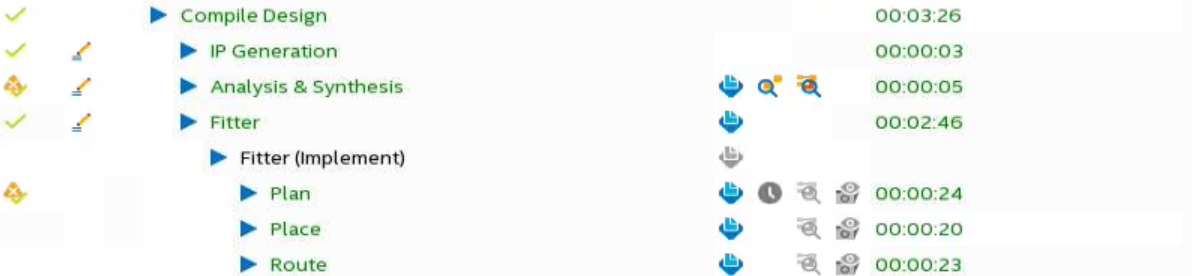
- Alternatively, if you have the flexibility of changing the non-migratable pins and their I/O standards, then you can go the Pin Migration View window and check the pins compatibility and assign the pins accordingly.
- The Pin Migration View window provides information about the suitability of the pins for device migration. You can open this window in the Pin Planner by clicking on View>Pin Migration View window. Select a pin in this view to display the following pin migration information:
- Pin number
- Migration devices
- Pin finder
- Migration result
- Show only highlighted pins
- Show migration differences
- Export
- Show commands
You can access these commands by using a right click on the Pin Migration View window in the Pin Planner.
You can see the difference and ease the pin assignment as shown in Figure 19. You can look into the pin finder to find the pins according to the requirement as shown in Figure 20.
Figure 19. Pin Migration View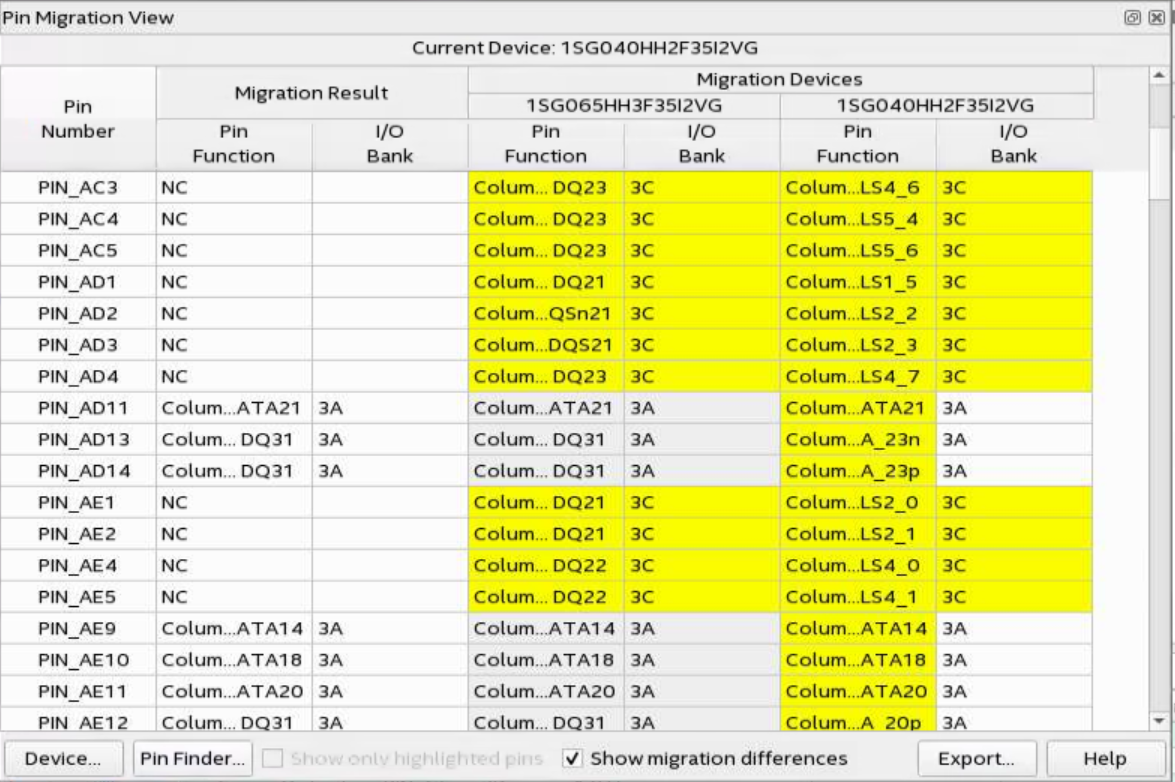 Figure 20. Pin Finder
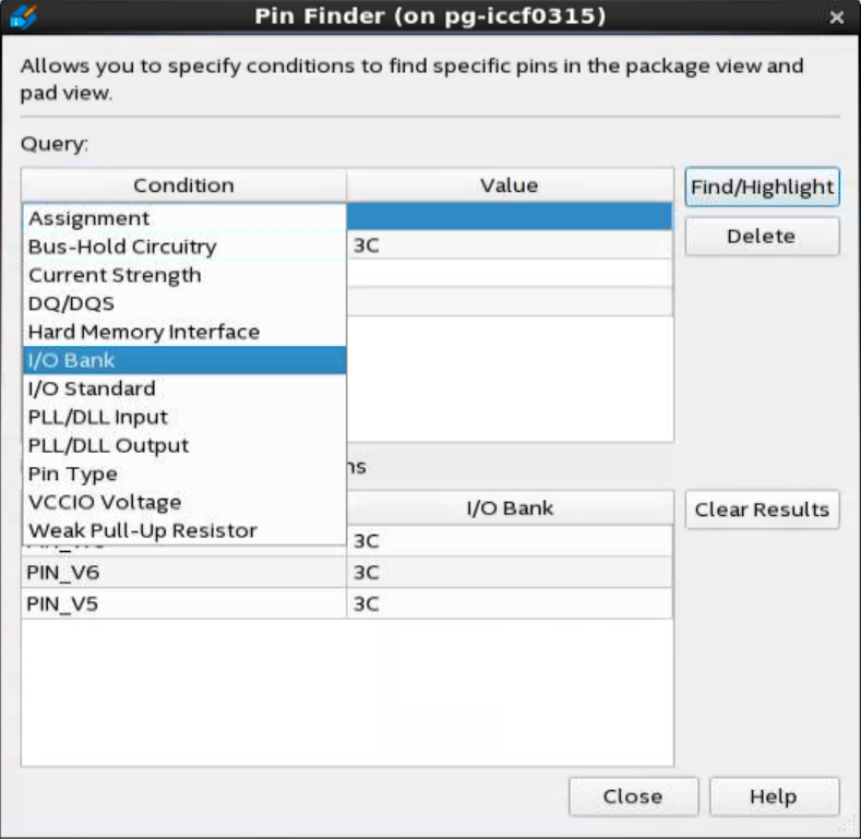
- Change the pin assignment as shown in the Figure 21 in the Pin Planner and compile the design. You will observe a successful compilation.
Figure 21. Pin Assignments