Test Engine FPGA IP User Guide: Agilex™ 5 and Agilex™ 7 FPGAs
A newer version of this document is available. Customers should click here to go to the newest version.
3.2.2. Memory AXI4 Driver Parameters

| Display Name | Description |
|---|---|
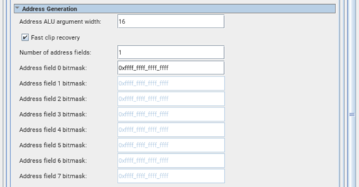
| Address ALU argument width | Specifies the width of the Address ALU. This affects the number of bits the Address ALU can change. Increasing this will allow wider ranges of address sweeping per command, but could degrade Fmax. The supported range for this parameter is from 1 to 44. Default value is 16. |
| Fast clip recovery | If enabled, address will reset to lower bound for 1 cycle when it exceeds upper bound, else it will reset to lower bound for 2 cycles – where lower bound is the minimum value of the defined address range, and upper bound is the maximum value of the defined address range. Enabling this can reduce latency for looped addresses, but can also degrade Fmax. |
| Number of address fields | Address fields allow updating selective bits (for example, field) within the address. The supported range for this parameter is from 1 to 8. Default value is 1. |
| Address field 0 bitmask | Update selective bits (for example, field) within the address by specifying a bitmask for the field. The main usage of address fields is to selectively choose which bits to affect. The supported range for this parameter is 0x0000_0000_0000_0000 to 0xffff_ffff_ffff_ffff. Default value is 0xffff_ffff_ffff_ffff. |
| Address field 1 bitmask | Update selective bits (i.e. field) within the address by specifying a bitmask for the field. The main usage of address fields is to selectively choose which bits to affect. The supported range for this parameter is 0x0000_0000_0000_0000 to 0xffff_ffff_ffff_ffff. Default value is 0xffff_ffff_ffff_ffff. |
| Address field 2 bitmask | Update selective bits (i.e. field) within the address by specifying a bitmask for the field. The main usage of address fields is to selectively choose which bits to affect. The supported range for this parameter is 0x0000_0000_0000_0000 to 0xffff_ffff_ffff_ffff. Default value is 0xffff_ffff_ffff_ffff. |
| Address field 3 bitmask | Update selective bits (i.e. field) within the address by specifying a bitmask for the field. The main usage of address fields is to selectively choose which bits to affect. The supported range for this parameter is 0x0000_0000_0000_0000 to 0xffff_ffff_ffff_ffff. Default value is 0xffff_ffff_ffff_ffff. |
| Address field 4 bitmask | Update selective bits (i.e. field) within the address by specifying a bitmask for the field. The main usage of address fields is to selectively choose which bits to affect. The supported range for this parameter is 0x0000_0000_0000_0000 to 0xffff_ffff_ffff_ffff. Default value is 0xffff_ffff_ffff_ffff. |
| Address field 5 bitmask | Update selective bits (i.e. field) within the address by specifying a bitmask for the field. The main usage of address fields is to selectively choose which bits to affect. The supported range for this parameter is 0x0000_0000_0000_0000 to 0xffff_ffff_ffff_ffff. Default value is 0xffff_ffff_ffff_ffff. |
| Address field 6 bitmask | Update selective bits (i.e. field) within the address by specifying a bitmask for the field. The main usage of address fields is to selectively choose which bits to affect. The supported range for this parameter is 0x0000_0000_0000_0000 to 0xffff_ffff_ffff_ffff. Default value is 0xffff_ffff_ffff_ffff. |
| Address field 7 bitmask | Update selective bits (i.e. field) within the address by specifying a bitmask for the field. The main usage of address fields is to selectively choose which bits to affect. The supported range for this parameter is 0x0000_0000_0000_0000 to 0xffff_ffff_ffff_ffff. Default value is 0xffff_ffff_ffff_ffff. |

| Display Name | Description |
|---|---|
| Number of DQ generators | Memory DQ pins can be driven by distinct pattern generators. If there are more DQ pins than generators, the patterns will be replicated. If there are fewer DQ pins than generators, the unused generators are discarded. The supported values for this parameter are: 1, 2, 4, 8, 16. Default value is 2. |
| Number of DM generators | Memory DM pins can be driven by distinct pattern generators. If there are more DM pins than generators, the patterns will be replicated. If there are fewer DM pins than generators, the unused generators are discarded. The supported values for this parameter are: 1, 2, 4, 8. Default value is 2. |
| AXI-data / Memory-DQ width ratio | Ratio between AXI data width and Memory DQ width, which affects the unroll factor of DQ and DM generators. (Memory-DQ Width Ratio = Data Width ÷ DQ Width). |

| Display Name | Description |
|---|---|
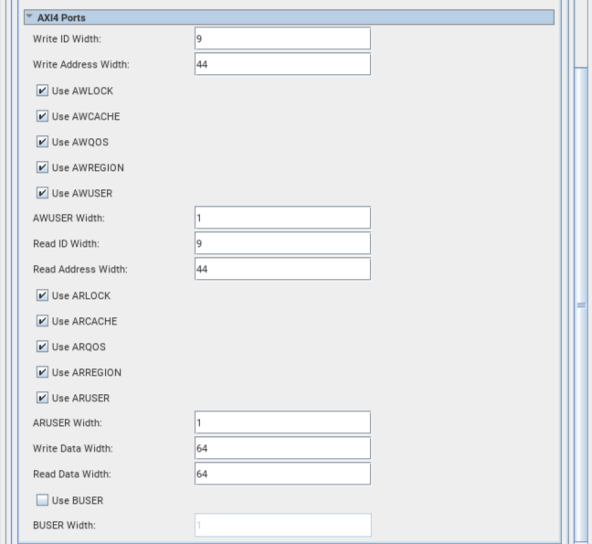
| Write ID Width | Specifies widths of AWID and BID ports of the AXI4 bus. The supported range for this parameter is from 1 to 18. Default value is 7. |
| Write Address Width | Specifies width of AWADDR port of the AXI4 bus. The supported range for this parameter is from 1 to 64. Default value is 31. |
| Use AWLOCK | Use AWLOCK port on the AXI4 bus. |
| Use AWCACHE | Use AWCACHE port on the AXI4 bus. |
| Use AWQOS | Use AWQOS port on the AXI4 bus. |
| Use AWREGION | Use AWREGION port on the AXI4 bus. |
| Use AWUSER | Use AWUSER port on the AXI4 bus. |
| AWUSER Width | Specifies width of AWUSER port of the AXI4 bus. The supported range for this parameter is from 1 to 64. Default value is 8. |
| Read ID Width | Specifies widths of ARID and RID ports of the AXI4 bus. The supported range for this parameter is from 1 to 18. Default value is 7. |
| Read Address Width | Specifies width of ARADDR port of the AXI4 bus. The supported range for this parameter is from 1 to 64. Default value is 31. |
| Use ARLOCK | Use ARLOCK port on the AXI4 bus. |
| Use ARCACHE | Use ARCACHE port on the AXI4 bus. |
| Use ARQOS | Use ARQOS port on the AXI4 bus. |
| Use ARREGION | Use ARREGION port on the AXI4 bus. |
| Use ARUSER | Use ARUSER port on the AXI4 bus. |
| ARUSER Width | Specifies width of ARUSER port of the AXI4 bus. The supported range for this parameter is from 1 to 64. Default value is 8. |
| Write Data Width | Specifies width of write data. 2^N bits are mapped to the WDATA port and the remaining bits, up to a maximum of 64, are mapped to WUSER port of the AXI4 Bus. N is an integer ranging from 3 to 10. The supported ranges for this parameter are from 8 to 192, 256 to 320, 512 to 576, and 1024 to 1088. |
| Read Data Width | Specifies width of read data. 2^N bits are mapped to the RDATA port and the remaining bits, up to a maximum of 64, are mapped to RUSER port of the AXI4 Bus. N is an integer ranging from 3 to 10. The supported ranges for this parameter are from 8 to 192, 256 to 320, 512 to 576, and 1024 to 1088. |
| Use BUSER | Use BUSER port on the AXI4 bus. |
| BUSER Width | Specifies width of BUSER port of the AXI4 bus. The supported range for this parameter is from 1 to 64. Default value is 8. |