Triple-Speed Ethernet Intel® FPGA IP User Guide: Agilex™ 3 and Agilex™ 5 FPGAs and SoCs
ID
813669
Date
4/07/2025
Public
A newer version of this document is available. Customers should click here to go to the newest version.
1. About Triple-Speed Ethernet Intel® FPGA IP for Agilex™ 3 and Agilex™ 5 devices
2. Getting Started
3. Parameter Settings
4. Functional Description
5. Configuration Register Space
6. Interface Signals
7. Design Considerations
8. Timing Constraints
9. Testbench
10. Triple-Speed Ethernet Debug Checklist
11. Software Programming Interface
12. Triple-Speed Ethernet Intel® FPGA IP User Guide: Agilex™ 3 and Agilex™ 5 FPGAs and SoCs Archives
13. Document Revision History for the Triple-Speed Ethernet Intel® FPGA IP User Guide: Agilex™ 3 and Agilex™ 5 FPGAs and SoCs
A. Ethernet Frame Format
B. Simulation Parameters
4.1.1. MAC Architecture
4.1.2. MAC Interfaces
4.1.3. MAC Transmit Datapath
4.1.4. MAC Receive Datapath
4.1.5. MAC Transmit and Receive Latencies
4.1.6. FIFO Buffer Thresholds
4.1.7. Congestion and Flow Control
4.1.8. Magic Packets
4.1.9. MAC Local Loopback
4.1.10. MAC Reset
4.1.11. PHY Management (MDIO)
4.1.12. Connecting MAC to External PHYs
6.1.1. 10/100/1000 Ethernet MAC Signals
6.1.2. 10/100/1000 Multiport Ethernet MAC Signals
6.1.3. 10/100/1000 Ethernet MAC with 1000BASE-X/SGMII PCS Signals
6.1.4. 10/100/1000 Ethernet MAC with Internal FIFO Buffers, and 1000BASE-X/SGMII 2XTBI PCS with Embedded PMA (GTS) Signals
6.1.5. 10/100/1000 Multiport Ethernet MAC with 1000BASE-X/SGMII PCS Signals
6.1.6. 1000BASE-X/SGMII PCS Signals
6.1.7. 1000BASE-X/SGMII PCS and PMA (LVDS) Signals
6.1.8. 1000BASE-X/SGMII 2XTBI PCS Signals
6.1.9. 10/100/1000 Ethernet MAC with 1000BASE-X/SGMII PCS and Embedded PMA (LVDS) Signals
6.1.10. 10/100/1000 Multiport Ethernet MAC with 1000BASE-X/SGMII PCS and Embedded PMA (LVDS) Signals
6.1.1.1. Clock and Reset Signals
6.1.1.2. Clock Enabler Signals
6.1.1.3. MAC Control Interface Signals
6.1.1.4. MAC Status Signals
6.1.1.5. MAC Receive Interface Signals
6.1.1.6. MAC Transmit Interface Signals
6.1.1.7. Pause and Magic Packet Signals
6.1.1.8. MII/GMII/RGMII Signals
6.1.1.9. PHY Management Signals
10.2.6. Link Synchronization
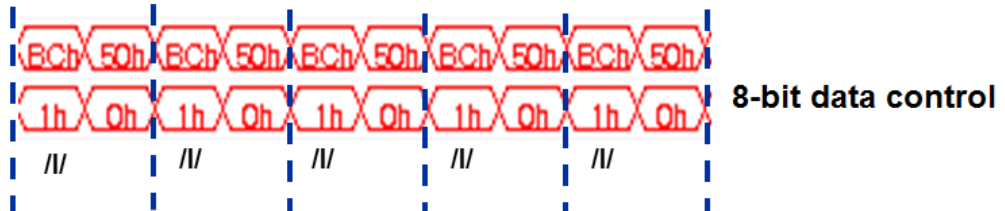
For link synchronization, ensure CDR is stable and word is aligned. Link synchronization can be achieved when 3 comma characters are received.
Example of the waveform on the transceiver interface (8-bit data):
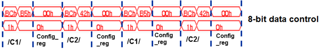
Example of the waveform on the transceiver interface (8-bit data) for /C1/ and /C2/ character configuration for auto-negotiation:
To investigate on the link synchronization issue:
- Check the transceiver/LVDS interface and ensure the PLL is locked and rxfreq_lock/rxlock_todata/rx_lock_to_ref are asserted.
- Check all resets and ensure the core is out of reset.
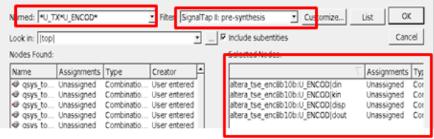
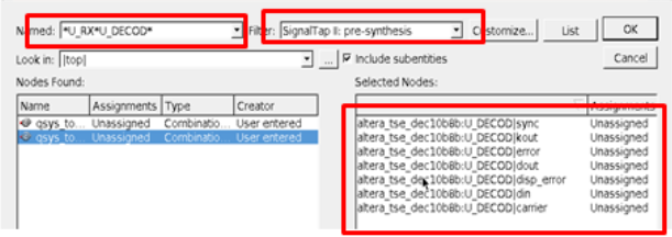
- Run Signal Tap on the state machine and set 8-bit interface data as the output for 8b/10b decoder. Use the keywords *U_TX*U_ENCOD and *U_RX*U_DECOD to find 8b/10b decoder and encoder nodes.
- Use the keyword *U_SYNC|state to find the state machine nodes.
Transceiver is not encrypted in the Triple-Speed Ethernet IP library (clear text RTL is provided). Use the following keywords:
- altera_tse_gxb_gige_inst (IV Series devices and below)
- altera_tse_gxb_gige_phyip_inst (V series devices)
Example issue: Ethernet link down intermittenly.
- Check the link and AN status:
- LED_LINK and LED_AN from the IP.
- PCS status register bit 2 for link status and bit 5 for AN complete.
- Check the transmit and receive data.
Root cause: The reset sequencer is repeatedly asserting the rx_digitalreset.
Example of the correct Signal Tap waveform: