Intel® Stratix® 10 H-tile and L-tile Avalon® Memory-mapped Hard IP for PCI Express* Design Example User Guide

ID 683616
Date 3/07/2022
Public

1.4. Generating the Design Example

Follow these steps to generate your design:
Figure 4. Procedure
  1. In the Intel® Quartus® Prime Pro Edition software, create a new project (File > New Project Wizard).
  2. Specify the Directory, Name, and Top-Level Entity.
  3. For Project Type, accept the default value, Empty project. Click Next.
  4. For Add Files click Next.
  5. For Family, Device & Board Settings under Family, select Intel® Stratix® 10 (GX/SX/MX/TX) and the Target Device for your design.
  6. Click Finish.
  7. In the IP Catalog, locate and add the Intel L-/H-Tile Avalon-MM for PCI Express IP.
  8. In the New IP Variant dialog box, specify a name for your IP. Click Create.
  9. On the IP Settings tabs, specify the parameters for your IP variation.
  10. On the Example Designs tab, make the following selections:
    1. For Available Example Designs, select DMA.
      Note: The DMA design example is only available when you turn on Enable Avalon® -MM DMA on the Avalon® -MM Settings tab.
      Note: If you do not turn on Enable Avalon® -MM DMA, you can still choose the PIO design example.
    2. For Example Design Files, turn on the Simulation and Synthesis options. If you do not need these simulation or synthesis files, leaving the corresponding option(s) turned off significantly reduces the example design generation time.
    3. For Generated HDL Format, only Verilog is available in the current release.
    4. For Target Development Kit, select the appropriate option.
      Note: If you select None, the generated design example targets the device you specified in Step 5 above. You cannot change the pin allocations of the Intel L-/H-Tile Avalon-MM for PCI Express IP in the Intel® Quartus® Prime project. However, this IP does support lane reversal and polarity inversion on the PCB by default.
  11. Select Generate Example Design to create a design example that you can simulate and download to hardware. If you select one of the Intel® Stratix® 10 development boards, the device on that board overwrites the device previously selected in the Intel® Quartus® Prime project if the devices are different. When the prompt asks you to specify the directory for your example design, you can accept the default directory, <example_design>/pcie_s10_hip_avmm_bridge_0_example_design, or choose another directory.
    Figure 5. Example Design Tab
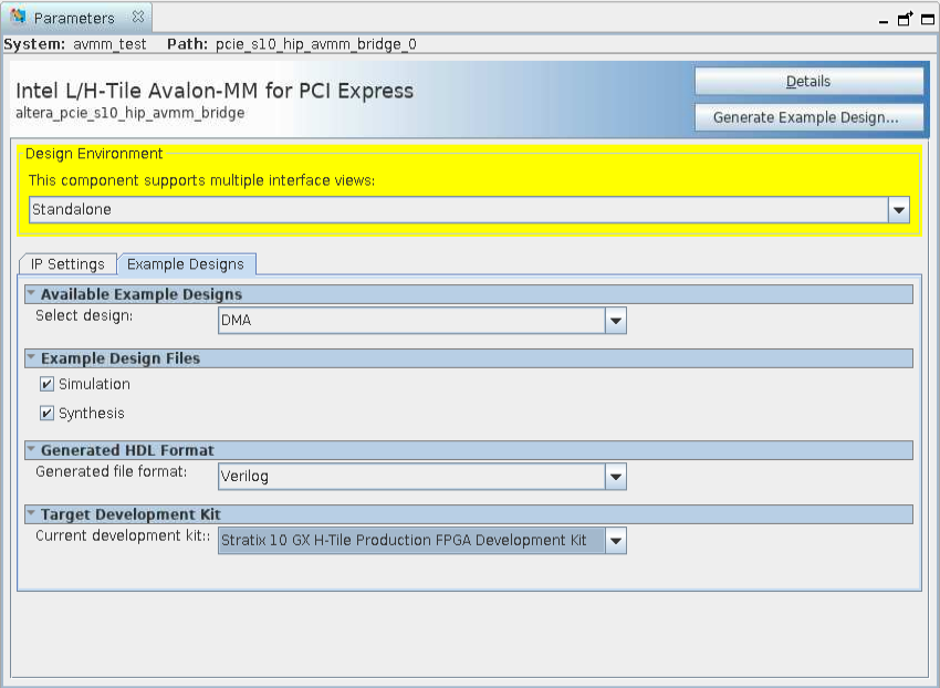
    When you generate an Intel® Stratix® 10 example design, a file called recommended_pinassignments_s10.txt is created in the directory pcie_s10_hip_avmm_bridge_0_example_design.1
  12. Click Finish. You may save your .ip file when prompted, but it is not required to be able to use the example design.
  13. The prompt, Recent changes have not been generated. Generate now?, allows you to create files for simulation and synthesis of the IP core variation that you specified in Step 9 above. Click No if you only want to work with the design example you have generated.
  14. Close the dummy project.
  15. Open the example design project.
  16. Compile the example design project to generate the .sof file for the complete example design. This file is what you download to a board to perform hardware verification.
  17. Close your example design project.
1 This file contains the recommended pin assignments for all the pins in the example design. If you select a development kit option in the pull-down menu for Target Development Kit, the pin assignments in the recommended_pinassignments_s10.txt file match those that are in the .qsf file in the same directory. If you chose NONE in the pull-down menu, the .qsf file does not contain any pin assignment. In this case, you can copy the pin assignments in the recommended_pinassignments_s10.txt file to the .qsf file. You can always change any pin assignment in the .qsf file to satisfy your design or board requirements.