A newer version of this document is available. Customers should click here to go to the newest version.
1. Answers to Top FAQs
2. Overview of the Intel® FPGA Power and Thermal Calculator
3. Estimating Power Consumption with the Intel® FPGA Power and Thermal Calculator
4. Intel® FPGA Power and Thermal Calculator Graphical User Interface
5. Intel® FPGA Power and Thermal Calculator Pages
6. Factors Affecting the Accuracy of the Intel® FPGA PTC
7. Intel® FPGA Power and Thermal Calculator User Guide Archive
8. Document Revision History for the Intel® FPGA Power and Thermal Calculator User Guide
A. Measuring Static Power
5.1. Intel® FPGA PTC - Power Summary
5.2. Intel® FPGA PTC - Common Page Elements
5.3. Intel® FPGA PTC - Main Page
5.4. Intel® FPGA PTC - Logic Page
5.5. Intel® FPGA PTC - RAM Page
5.6. Intel® FPGA PTC - DSP Page
5.7. Intel® FPGA PTC - Clock Page
5.8. Intel® FPGA PTC - PLL Page
5.9. Intel® FPGA PTC - I/O Page
5.10. Intel® FPGA PTC - Transceiver Page
5.11. Intel® FPGA PTC - HPS Page
5.12. Intel® FPGA PTC - Crypto Page
5.13. Intel® FPGA PTC - HBM Page
5.14. Intel® FPGA PTC - Thermal Page
5.15. Intel® FPGA PTC - Report Page
5.15. Intel® FPGA PTC - Report Page
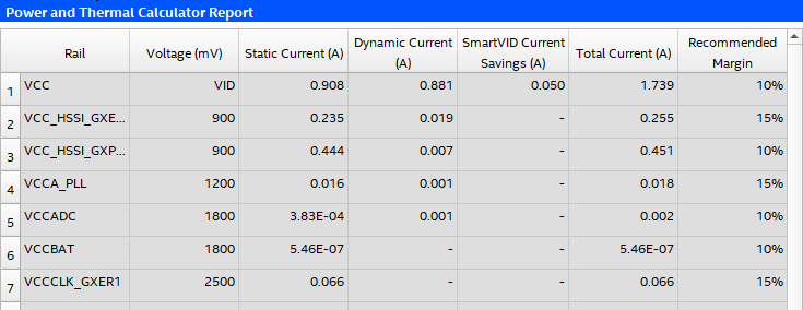
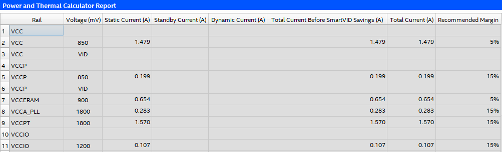
The Report page shows per-rail currents that the Intel® FPGA Power and Thermal Calculator (PTC) calculates.
Figure 40. Report Page of the Intel® FPGA PTC
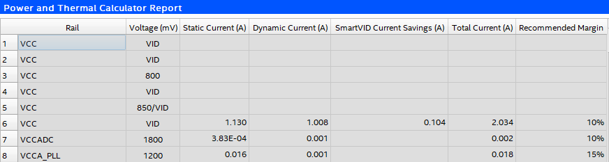
The Report page provides current requirements for each voltage rail, expressed in terms of static current, dynamic current, and total current.
There is a minor difference in the format of the Report page between Intel® Agilex™ and Intel® Stratix® 10 device families:
- For Intel® Agilex™ device families, every row displayed in the Report table represents a corresponding voltage rail.
- For Intel® Stratix® 10 devices, different sections of the table are preceded by an empty row. For example, an empty VCC row introduces the VCC section of the table, an empty VCCIO row introduces the VCCIO section, and so forth.
For the Power and Thermal Calculator Report table, you can press the F5 key to resize the rows to be the same height as other rows.
| Column Heading | Description |
|---|---|
| Rail | Name of the voltage rail. |
| Voltage (mV) | Rail voltage. |
| Static Current (A) | Indicates the component of current consumed from the specified power rail whenever the power is applied to the rail, independent of circuit activity (in A). This current is dependent on device size, device grade, power characteristics and junction temperature. |
| Standby Current (A) | Indicates the component of active current drawn from the specified power rail by all modules on all pages, independent of signal activity (in A). This current is independent of device grade, power characteristics and junction temperature. Standby current includes, but is not limited to, I/O and transceiver DC bias current. Device size has only a small impact on transceiver DC bias current. (This column applies only to Intel® Stratix® 10 devices.) |
| Dynamic Current (A) | Indicates the component of active current drawn from the specified power rail due to signal activity of all modules on all pages (in A). This current depends on device size, but is independent of device grade, power characteristics and junction temperature. |
| SmartVID Current Savings (A) | Indicates the total current saved from the specified power rail due to SmartVID savings (in A). (This column applies only to Intel® Agilex™ devices.) |
| Total Current Before SmartVID Savings (A) | Indicates the total current consumed from the specified power rail before SmartVID savings (in A). The sum of static, standby, and dynamic currents. (This column applies only to Intel® Stratix® 10 devices.) |
| Total Current (A) | Indicates the total current consumed from the specified power rail (in A). For devices and rails supporting SmartVID, this column shows total current after SmartVID current savings; otherwise, the current reported in this column should equal the sum of static and dynamic currents (for Intel® Agilex™ devices, or the sum of static, standby, and dynamic currents (for Intel® Stratix® 10 devices). |
| Recommended Margin | Indicates the recommended margin on total current for regulator sizing. The recommended margin on the Vcc rail is calculated based on the ratio of dynamic to static power. |