Device-Specific Power Delivery Network (PDN) Tool 2.0 User Guide
1.2.3.1. Pre-Layout Instructions
The PDN tool 2.0 provides an accurate estimate of the number and types of capacitors needed to design a robust power delivery network, regardless of where you are in the design phase. However, the accuracy of the results depends highly on your inputs for the various parameters.
If you have finalized the board stackup and have access to board database and layout information, you can proceed through the tabs and enter the required information to arrive at an accurate decoupling scheme.
In the pre-layout phase of the design cycle when you do not have specific information about the board stack-up and board layout, you can follow these instructions to explore the solution space when finalizing key design parameters such as stackup, plane size, capacitor count, capacitor orientation, and so on.
In the pre-layout phase, ignore the Plane Cap and Cap Mount tabs and go directly to the Library tab when you do not have the layout information. If available, enter the values shown below in the Library tab. To use the default values, go directly to the System_Decap tab to begin the analysis.
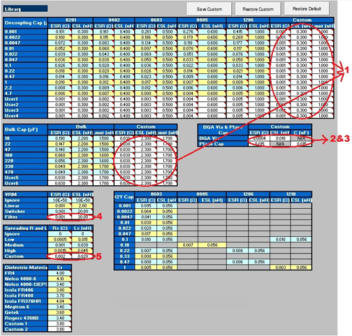
- Enter the ESR, ESL, and Lmnt values for the capacitors listed in the Custom field.
- Enter the effective BGA via parasitics for the power supply being decoupled in the BGA Via & Plane Cap field.
- Enter the plane capacitance seen by the power/ground plane pair on the board for the power supply in the BGA Via & Plane Cap field.
- Enter the VRM parasitics, if available, in the Custom row of the VRM field.
- Enter the effective spreading inductance seen by the decoupling capacitors in the Custom row of the Spreading R and L field.