Device-Specific Power Delivery Network (PDN) Tool 2.0 User Guide
ID
683293
Date
8/24/2021
Public
1.2.2.1.1. Device Selection Section
1.2.2.1.2. Power Rail Data and Configuration Section
1.2.2.1.3. Meeting Target Impedance when Entering 0 A into the PDN Tool
1.2.2.1.4. Dealing with Multiple Shared Power Supply Pin Types
1.2.2.1.5. VRM Data Section
1.2.2.1.6. Rail Group Summary Section
1.2.2.1.7. VRM Impedance Section
1.2.2.1.8. BGA Via Section
1.2.2.1.9. Plane Section
1.2.2.1.10. Spreading Section
1.2.2.1.11. Implementing Split Planes
1.2.2.1.12. FEFFECTIVE Section
1.2.2.1.13. Decoupling Section
1.2.2.1.14. Results Summary Section
1.2.2.1.15. Recommended Flow for Deriving Decoupling for an FPGA System using the System_Decap Tab
1.2.2.4. Plane_Cap
The Plane Cap tab calculates the distributed plane capacitance in microfarads (µF) that is developed between the power/ground planes based on the parallel plate capacitor equation.
Figure 16. Plane_Cap Tab
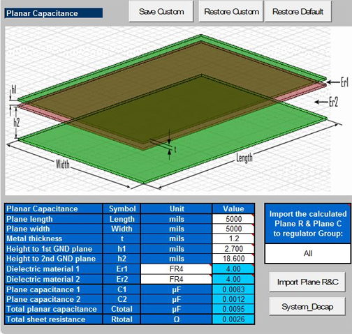
Enter the design specific information such as plane dimensions, plane configuration and the dielectric material used in the Planar Capacitance table. The tool calculates a plane capacitance value. You can save custom values, restore custom values, or restore the default settings.
The Import Plane R&C button inserts the data for the planar capacitance into the regulator group data.