1G/2.5G/5G/10G Multirate Ethernet PHY IP User Guide: Agilex™ 3 and Agilex™ 5 FPGAs and SoCs
ID
813667
Date
10/24/2025
Public
1. About the 1G/2.5G/5G/10G Multirate Ethernet PHY IP for Agilex™ 3 and Agilex™ 5 Devices
2. Getting Started
3. Functional Description
4. Parameter Settings for 1G/2.5G/5G/10G Multirate Ethernet PHY IP
5. Interface Signals
6. Configuration Registers
7. Troubleshooting and Debugging Diagnostics
8. 1G/2.5G/5G/10G Multirate Ethernet PHY IP User Guide: Agilex™ 3 and Agilex™ 5 FPGAs and SoCs Archives
9. Document Revision History for the 1G/2.5G/5G/10G Multirate Ethernet PHY IP User Guide: Agilex™ 3 and Agilex™ 5 FPGAs and SoCs
3.2.1.1. Step 1: Generating the 1G/2.5G/5G/10G Multirate Ethernet PHY IP
3.2.1.2. Step 2: QSF settings and Dynamic Reconfiguration (DR) profile assignments
3.2.1.3. Step 3: RTL Generation using Quartus® Prime Pro Edition Tool
3.2.1.4. Step 4: Instantiate the IP top file with the GTS Dynamic Reconfiguration Controller IP
5.1. Clock Signals
5.2. Reset Signals
5.3. Serial Interface Signals
5.4. Avalon Memory-Mapped Interface Signals
5.5. XGMII Signals
5.6. GMII Signals
5.7. PHY Status Signals
5.8. Transceiver Mode and Operating Speed Signals
5.9. Transceiver Status and Reconfiguration Signals
5.10. GTS Reset Sequencer Signals
5.11. Dynamic Reconfiguration Controller Interface Signals
4.2. Analog Parameters
Figure 19. Analog Parameters Tab (NBASE PHY)
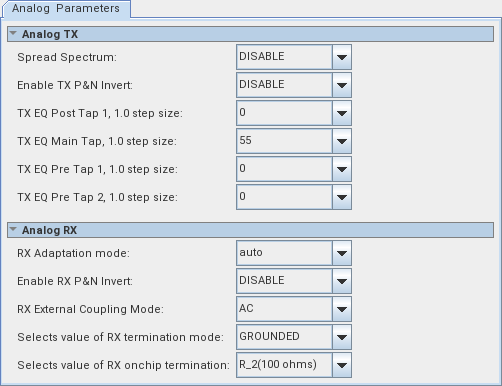
Figure 20. Analog Parameter Tab (MGBASE PHY)
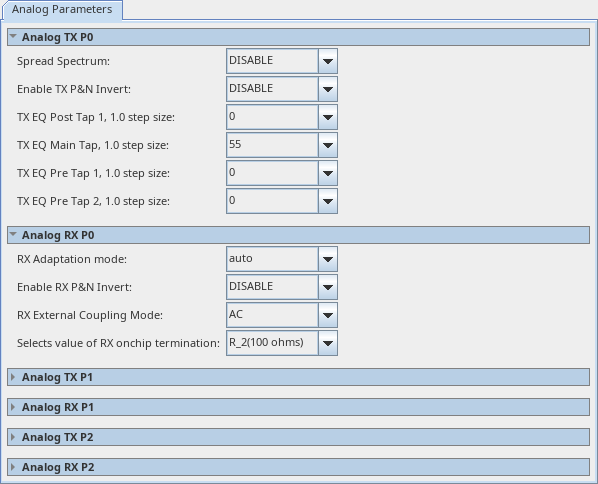
Note: For 1G and 2.5G MGBASE, the RX Adaptation mode is set to manual. For 10G MGBASE, the RX Adaptation mode is set to auto.
For more information on the analog parameter configuration, refer to Configurable Quartus® Prime Software Settings in the GTS Transceiver PHY User Guide.