AN 994: Drive-on-Chip Design Example for Intel Agilex® 7 Devices
1. About the Drive-on-Chip Design Example for Intel Agilex® 7 Devices
| Updated for: |
|---|
| Intel® Quartus® Prime Design Suite 23.1 |
The design includes a motor and power board model that removes the need for a physical motor setup. The design synthesizes and programs the model in the same FPGA. The model is a DSP Builder for Intel FPGAs design.
You only need an Intel Agilex® 7 FPGA Development Kit to run the design. The motor and power board model helps to tune and test the control system before using a physical power stage.
The figure shows a top-level diagram of the design's hardware that demonstrates dual-axis control using an Intel® FPGA.
Supported FPGA Development Kits
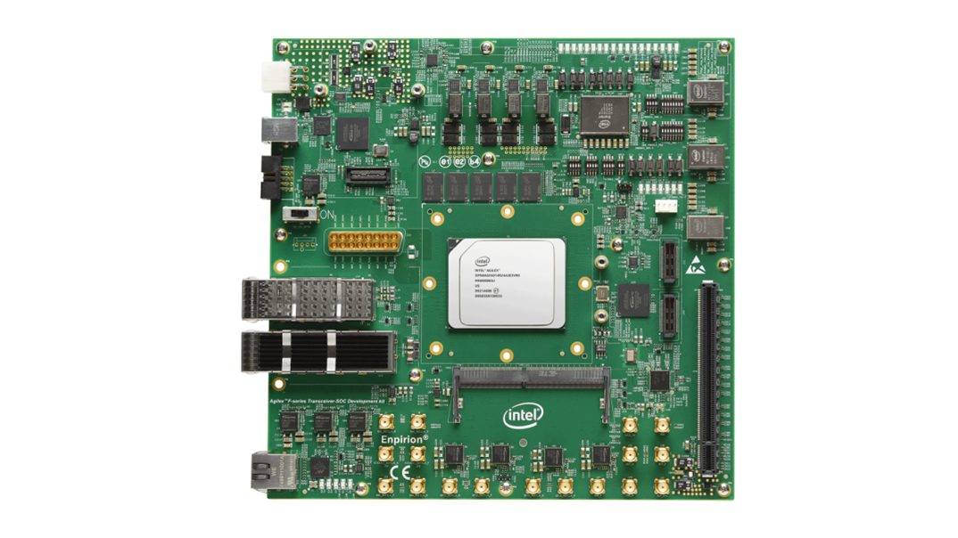
The design supports the Rev C (or later) Intel Agilex® 7 F-series Transceiver-SoC Development Kit. You can modify the design to run it on other Intel FPGA development kits.
Supported Motor Control Board
The motor and power board model is based on the Tandem Motion 48 V power board (refer to refer to AN773 and AN669). You can parameterize the design to operate with various physical motors and power boards. As the design includes a motor and power board model, you do not need physical motors or a power board to run this design, only the development kit.
AC and Servo Drive Systems
AC and servo drive system designs comprise multiple distinct but interdependent functions to realize requirements and meet the performance and efficiency demands of modern motor control systems. The system's primary function is to efficiently control the torque and speed of the AC motor through appropriate control of power electronics. A typical drive system includes:
- Flexible pulse-width modulation (PWM) circuitry to switch the power stage transistors appropriately.
- Motor control loops for single or multiaxis control
- Industrial networking interfaces
- Position encoder interfaces
- Current, voltage, and temperature measurement feedback elements.
- Monitoring functions, for example, for vibration suppression.
The system requires software running on a processor for high-level system control, coordination, and management.
Intel Agilex® 7 Devices and DSP Builder for Intel FPGAs
Intel Agilex® 7 devices offer high-performance fixed- and floating-point DSP functionality and can include Nios V/g soft processors. Intel FPGA devices offer a scalable and flexible platform for integration of single- and multiaxis drives on a single device.
This design comprises FPGA IP, a Nios V soft processor running software libraries, and a hardware platform. The design demonstrates DSP Builder for Intel FPGAs and Platform Designer tools for system integration of IP, bus connections, and includes the Nios V/g soft processor. The design includes all software and IP components. You can extend and customize the design to meet your own application needs. The design supports partitioning of algorithms between software running on an integrated processor, and IP performing portions of the motor control algorithm in the FPGA, to accelerate performance.
Additionally, the design includes a DSP Builder based IP model for a physical motor and power board in the Platform Designer project. This model removes the need for a real motor rig and provides elements to adjust the model to the parameters of other commercial motors and power stages and substitute the IP with a physical setup.
Depending on your system performance requirements or the number of axes you need to support, this design allows you to implement the FOC loop in DSP Builder-designed hardware, or in software on the Nios V/g processor. The design allows you to connect to the motor and power stages through on- or off-chip ADCs, feedback encoder devices, and transistor gate drive circuitry. You can connect to higher-level automation controllers by adding off-the-shelf IP, for example for industrial Ethernet or controller area network (CAN).