External Memory Interfaces Intel Agilex® 7 M-Series FPGA IP Design Example User Guide
ID
772632
Date
4/03/2023
Public
A newer version of this document is available. Customers should click here to go to the newest version.
1. About the External Memory Interfaces Intel Agilex® 7 M-Series FPGA IP
2. Design Example Quick Start Guide for External Memory Interfaces Intel Agilex® 7 M-Series FPGA IP
3. Design Example Description for External Memory Interfaces Intel Agilex® 7 M-Series FPGA IP
4. Document Revision History for External Memory Interfaces Intel Agilex® 7 M-Series FPGA IP Design Example User Guide
2.1. Creating an EMIF Project
2.2. Generating and Configuring the EMIF IP
2.3. Configuring DQ Pin Swizzling
2.4. Generating the Synthesizable EMIF Design Example
2.5. Generating the EMIF Design Example for Simulation
2.6. Pin Placement for Intel Agilex® 7 M-Series EMIF IP
2.7. Compiling the Intel Agilex® 7 M-Series EMIF Design Example
2.1.1.3.1. Generating a Custom Memory Preset File for DDR4
2.1.1.3.2. Guidelines for Selecting the DDR4 DRAM Component Package Type
2.1.1.3.3. Generating a Custom Memory Preset File for DDR5
2.1.1.3.4. Guidelines for Selecting the DDR5 DRAM Component Package Type
2.1.1.3.5. Generating a Custom Memory Preset File for LPDDR5
2.1.1.3.3. Generating a Custom Memory Preset File for DDR5
To generate a custom preset file for DDR5, follow these steps:
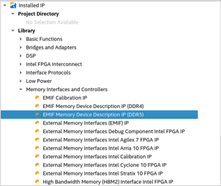
- In the IP Catalog window, select Memory Device Description IP (DDR5).
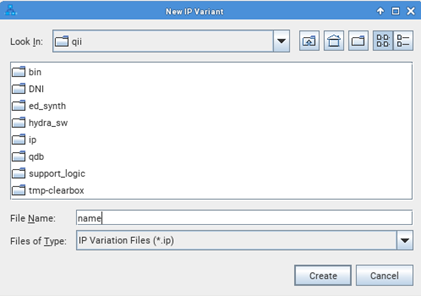
- Type the name for the IP instance and click Create.
- Refer to the images below for the steps in creating and saving the custom presets file:
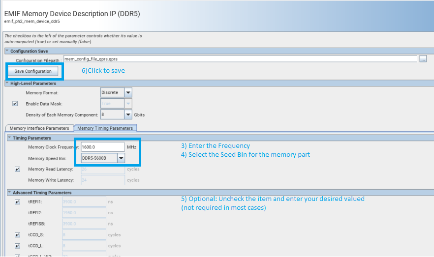
Figure 13. Parameterizing EMIF Memory Device Description IP (DDR5) – Part 1
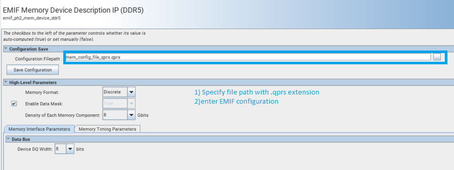 Figure 14. Parameterizing EMIF Memory Device Description IP (DDR5) – Part 2