AN 942: Signal Tap Tutorial with Design Block Reuse: for Intel® Agilex™ F-Series FPGA Development Board
ID
709306
Date
12/10/2021
Public
1. Introduction
2. Core Partition Reuse Debug—Developer
3. Core Partition Reuse Debug—Consumer
4. Root Partition Reuse Debug—Developer
5. Root Partition Reuse Debug—Consumer
6. Document Revision History for AN 942: Signal Tap Tutorial with Design Block Reuse for Intel® Agilex™ F-Series FPGA Development Board
2.1. Step 1: Creating a Core Partition
2.2. Step 2: Creating Partition Boundary Ports
2.3. Step 3: Compiling and Checking Debug Nodes
2.4. Step 4: Exporting the Core Partition and Creating the Black Box File
2.5. Step 5: Copying Files to Consumer Project
2.6. Step 6: Creating a Signal Tap File (Optional)
2.7. Step 7: Programming the Device and Verifying the Hardware
2.8. Step 8: Verifying Hardware with Signal Tap
3.1. Step 1: Adding Files and Running Synthesis
3.2. Step 2: Creating a Signal Tap File
3.3. Step 3: Creating a Partition for blinking_led_top
3.4. Step 4: Compiling the Design and Verifying Debug Nodes
3.5. Step 5: Programming the Device and Verifying the Hardware
3.6. Step 6: Verifying Hardware with Signal Tap
4.1. Step 1: Creating a Reserved Core Partition and Defining a Logic Lock Region
4.2. Step 2: Generating and Instantiating SLD JTAG Bridge Agent in the Root Partition
4.3. Step 3: Generating and Instantiating the SLD JTAG Bridge Host
4.4. Step 4: Generating HDL Instance of Signal Tap
4.5. Step 5: Compiling Export Root Partition and Copying Files to Consumer Project
4.6. Step 6: Programming the Device and Verifying the Hardware
4.7. Step 7: Generating a Signal Tap File for the Root Partition
4.8. Step 8: Verifying the Hardware with Signal Tap
5.1. Step 1: Adding Files to Customer Project
5.2. Step 2: Generating and Instantiating SLD JTAG Bridge Host in Reserved Core Partition
5.3. Step 3: Synthesizing, Creating Signal Tap File, and Compiling
5.4. Step 4: Programming the Device and Verifying the Hardware
5.5. Step 5: Verifying the Hardware of Reserved Core Partition with Signal Tap
5.6. Step 6: Verifying Hardware of Root Partition with Signal Tap
2.4. Step 4: Exporting the Core Partition and Creating the Black Box File
After compilation, you export the core partition and create a supporting black box port definitions file. This tutorial reuses the final compilation snapshot.
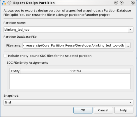
- Click Project > Export Design Partition. Select blinking_led_top for the Partition name, and the final Snapshot for export.
- Confirm blinking_led_top.qdb as the Partition Database File name and click OK. The final blinking_led.qdb that you export preserves the place and route data from the Developer project.
- To create the black box file, click File > New, select SystemVerilog HDL File under Design Files, and then click OK. A blank .sv file opens to allow you to enter the port definitions for the partition you export and the partition boundary ports created in Step 3: Compiling and Checking Debug Nodes.
- Include Verilog parameters or VHDL generics in the definition. The port definitions in the black box file must match the original, without the logic RTL.
module blinking_led_top( output [3:0] value, input clock, output db_count_0, output db_count_1, output db_count_2, output db_count_24, output db_value_0, output db_value_1, output db_value_2, output db_value_3 ); endmodule - Save the black box file as blinking_led_top_bb.sv. Turn off the option to Add file to current project.