Ethernet Link Inspector User Guide for Intel® Stratix® 10 Devices
ID
683367
Date
7/01/2019
Public
3.1.1. Link Monitor Tabs and Settings
The Link Monitor module of the Ethernet Link Inspector has three tabs. Each tab implements various Control and Status Registers (CSR) of the selected Ethernet IP core. There is also a Continuous Read All Registers option, which continuously polls the status of all the tabs.
| Tab | Description |
|---|---|
| MAC & PCS | Resets the IP core, reads the MAC configuration and checks the high level PCS status.
|
| Statistics |
|
| PMA |
|
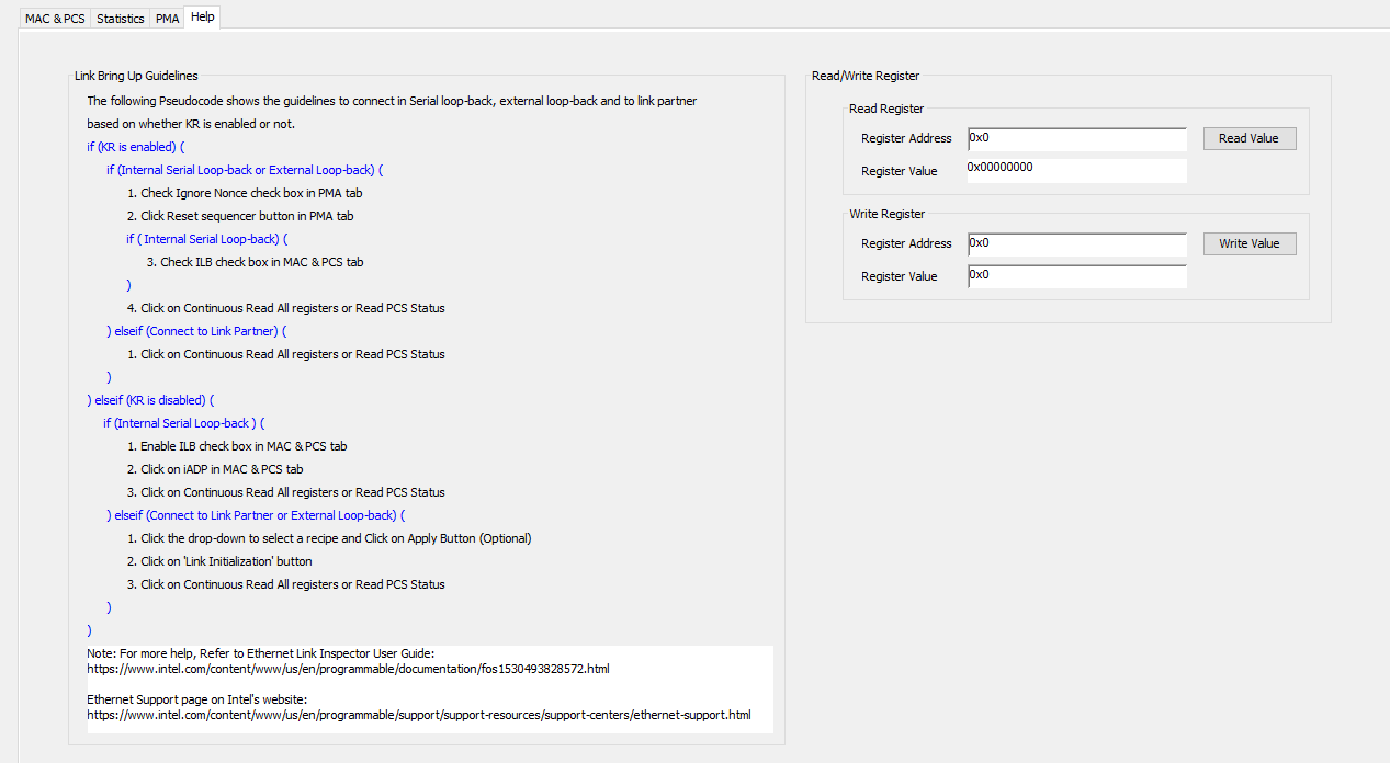
| Help | Displays link bring up guidelines |
The following figures show the Link Monitor GUI tabs and are related to the 25G E-tile Hard IP for Ethernet Intel® FPGA IP. The availability of each tab depends on IP selection and its features.
Figure 2. Example MAC & PCS Tab
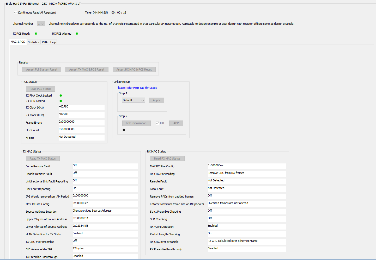
Figure 3. Example Statistics Tab
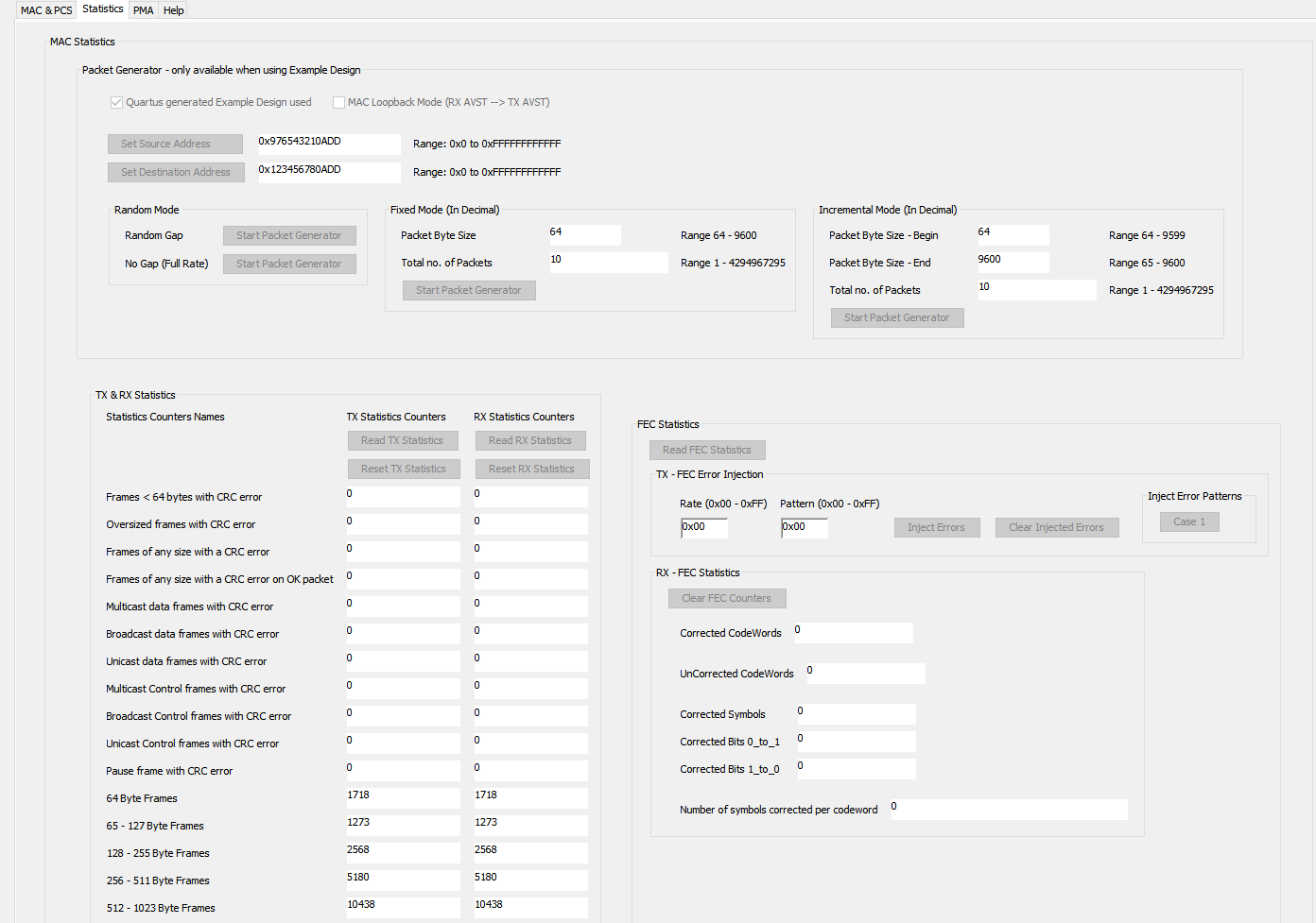
Figure 4. Example PMA Tab
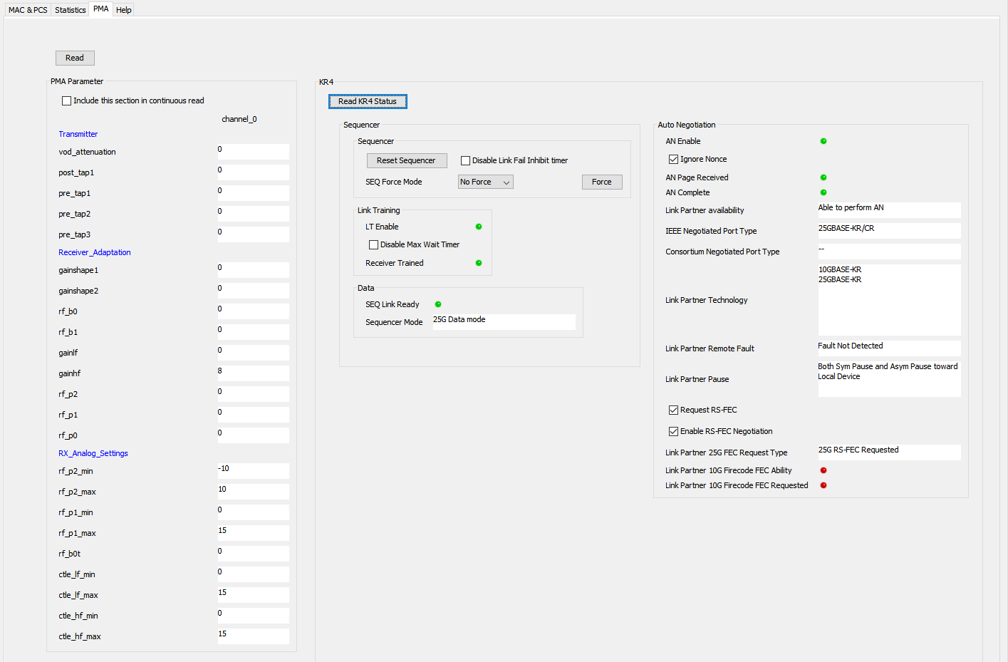
Figure 5. Example Help TabThe Read/Write Register section allows you to read and write values from and to the registers. Register address starts with 0x followed by the effective address. The address includes base address, word offset, and channel offset.