Interoperability with OpenMP* API
I_MPI_PIN_DOMAIN
Intel® MPI Library provides an additional environment variable to control main thread pinning for hybrid MPI/OpenMP* applications. This environment variable is used to define a number of non-overlapping subsets (domains) of logical processors on a node, and a set of rules on how MPI processes are bound to these domains by the following formula: one MPI process per one domain. See the picture below.
Figure 1 Domain Example
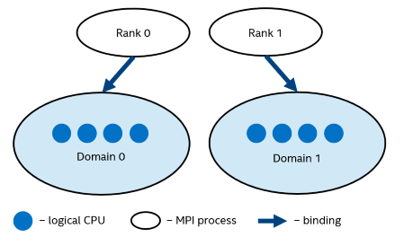
Each MPI process can create a number of children threads for running within the corresponding domain. The process threads can freely migrate from one logical processor to another within the particular domain.
If the I_MPI_PIN_DOMAIN environment variable is defined, then the I_MPI_PIN_PROCESSOR_LIST environment variable setting is ignored.
If the I_MPI_PIN_DOMAIN environment variable is not defined, then MPI main threads are pinned according to the current value of the I_MPI_PIN_PROCESSOR_LIST environment variable.
The I_MPI_PIN_DOMAIN environment variable has the following syntax forms:
Domain description through multi-core terms <mc-shape>
Domain description through domain size and domain member layout <size>[:<layout>]
Explicit domain description through bit mask <masklist>
The following tables describe these syntax forms.
Multi-Core Shape
I_MPI_PIN_DOMAIN=<mc-shape>
| <mc-shape> | Define domains through multi-core terms. |
| core | Each domain consists of the logical processors that share a particular core. The number of domains on a node is equal to the number of cores on the node. |
| socket | sock | Each domain consists of the logical processors that share a particular socket. The number of domains on a node is equal to the number of sockets on the node. This is the recommended value. |
| numa | Each domain consists of the logical processors that share a particular NUMA node. The number of domains on a machine is equal to the number of NUMA nodes on the machine. |
| node | All logical processors on a node are arranged into a single domain. |
| cache1 | Logical processors that share a particular level 1 cache are arranged into a single domain. |
| cache2 | Logical processors that share a particular level 2 cache are arranged into a single domain. |
| cache3 | Logical processors that share a particular level 3 cache are arranged into a single domain. |
| cache | The largest domain among cache1, cache2, and cache3 is selected. |
Explicit Shape
I_MPI_PIN_DOMAIN=<size>[:<layout>]
| <size> | Define a number of logical processors in each domain (domain size) |
| omp | The domain size is equal to the OMP_NUM_THREADS environment variable value. If the OMP_NUM_THREADS environment variable is not set, each node is treated as a separate domain. |
| auto | The domain size is defined by the formula size=#cpu/#proc, where #cpu is the number of logical processors on a node, and #proc is the number of the MPI processes started on a node |
| <n> | The domain size is defined by a positive decimal number <n> |
| <layout> | Ordering of domain members. The default value is compact |
| platform | Domain members are ordered according to their BIOS numbering (platform-depended numbering) |
| compact | Domain members are located as close to each other as possible in terms of common resources (cores, caches, sockets, and so on). This is the default value |
| scatter | Domain members are located as far away from each other as possible in terms of common resources (cores, caches, sockets, and so on) |
Explicit Domain Mask
I_MPI_PIN_DOMAIN=<masklist>
| <masklist> | Define domains through the comma separated list of hexadecimal numbers (domain masks) |
| [m1,...,mn] | For <masklist>, each mi is a hexadecimail bit mask defining an individual domain. The following rule is used: the ith logical processor is included into the domain if the corresponding mi value is set to 1. All remaining processors are put into a separate domain. BIOS numbering is used.
NOTE:
To ensure that your configuration in <masklist> is parsed correctly, use square brackets to enclose the domains specified by the <masklist>. For example: I_MPI_PIN_DOMAIN=[55,aa]
|
To pin OpenMP* processes or threads inside the domain, the corresponding OpenMP feature (for example, the KMP_AFFINITY environment variable for Intel® compilers) should be used.
See the following model of a symmetric multiprocessing (SMP) node in the examples:
Figure 2 Model of a Node
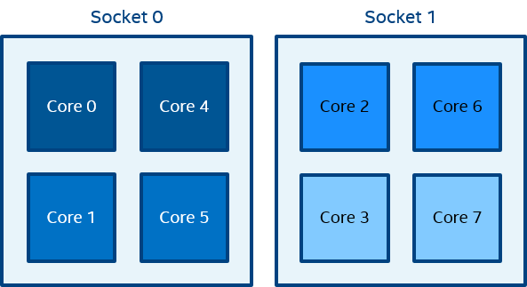
The figure above represents the SMP node model with a total of 8 cores on 2 sockets. Intel® Hyper-Threading Technology is disabled. Core pairs of the same color share the L2 cache.
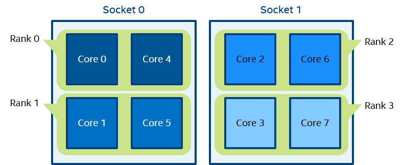
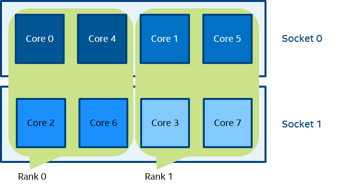
Figure 3 mpiexec -n 2 -env I_MPI_PIN_DOMAIN socket test.exe
In Figure 3, two domains are defined according to the number of sockets. Process rank 0 can migrate on all cores on the 0-th socket. Process rank 1 can migrate on all cores on the first socket.
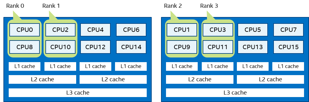
Figure 4 mpiexec -n 4 -env I_MPI_PIN_DOMAIN cache2 test.exe
In Figure 4, four domains are defined according to the amount of common L2 caches. Process rank 0 runs on cores {0,4} that share an L2 cache. Process rank 1 runs on cores {1,5} that share an L2 cache as well, and so on.
Figure 5 mpiexec -n 2 -env I_MPI_PIN_DOMAIN 4:platform test.exe
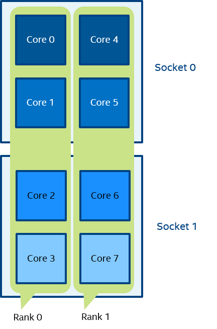
In Figure 5, two domains with size=4 are defined. The first domain contains cores {0,1,2,3}, and the second domain contains cores {4,5,6,7}. Domain members (cores) have consecutive numbering as defined by the platform option.
Figure 6 mpiexec -n 4 -env I_MPI_PIN_DOMAIN auto:scatter test.exe
In Figure 6, domain size=2 (defined by the number of CPUs=8 / number of processes=4), scatter layout. Four domains {0,2}, {1,3}, {4,6}, {5,7} are defined. Domain members do not share any common resources.
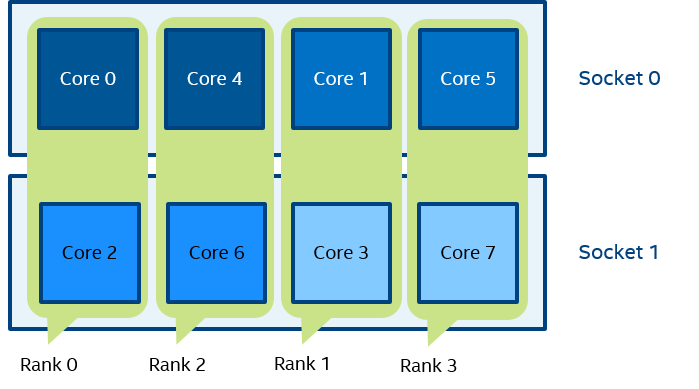
Figure 7 set OMP_NUM_THREADS=2 mpiexec -n 4 -env I_MPI_PIN_DOMAIN omp:platform test.exe
In Figure 7, domain size=2 (defined by OMP_NUM_THREADS=2), platform layout. Four domains {0,1}, {2,3}, {4,5}, {6,7} are defined. Domain members (cores) have consecutive numbering.
Figure 8 mpiexec -n 2 -env I_MPI_PIN_DOMAIN [55,aa] test.exe
In Figure 8 (the example for I_MPI_PIN_DOMAIN=<masklist>), the first domain is defined by the 55 mask. It contains all cores with even numbers {0,2,4,6}. The second domain is defined by the AA mask. It contains all cores with odd numbers {1,3,5,7}.
I_MPI_PIN_ORDER
Set this environment variable to define the mapping order for MPI processes to domains as specified by the I_MPI_PIN_DOMAIN environment variable.
Syntax
I_MPI_PIN_ORDER=<order>
Arguments
| <order> | Specify the ranking order |
| range | The domains are ordered according to the processor's BIOS numbering. This is a platform-dependent numbering. |
| scatter | The domains are ordered so that adjacent domains have minimal sharing of common resources, whenever possible. |
| compact | The domains are ordered so that adjacent domains share common resources as much as possible. |
| spread | The domains are ordered consecutively with the possibility not to share common resources. |
| bunch | The processes are mapped proportionally to sockets and the domains are ordered as close as possible on the sockets. This is the default value. |
Description
The optimal setting for this environment variable is application-specific. If adjacent MPI processes prefer to share common resources, such as cores, caches, sockets, FSB, use the compact or bunch values. Otherwise, use the scatter or spread values. Use the range value as needed. For detail information and examples about these values, see the Arguments table and the Example section of I_MPI_PIN_ORDER in this topic.
The options scatter, compact, spread and bunch are available for both Intel® and non-Intel microprocessors, but they may perform additional optimizations for Intel microprocessors than they perform for non-Intel microprocessors.
Examples
For the following configuration:
Two socket nodes with four cores and a shared L2 cache for corresponding core pairs.
4 MPI processes you want to run on the node using the settings below.
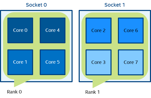
Compact order:
I_MPI_PIN_DOMAIN=2 I_MPI_PIN_ORDER=compact
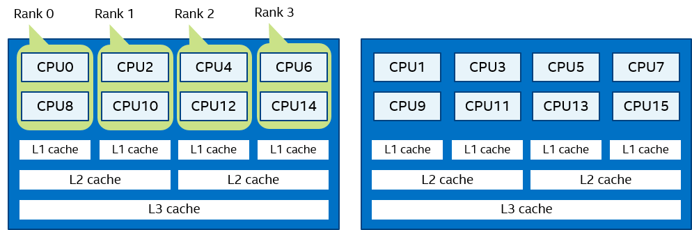
Figure 9 Compact Order Example
Scatter order:
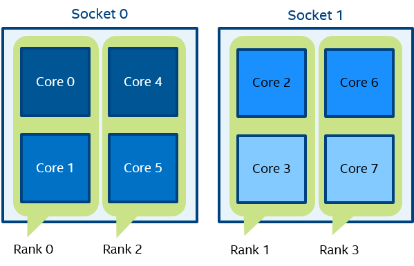
I_MPI_PIN_DOMAIN=2 I_MPI_PIN_ORDER=scatter
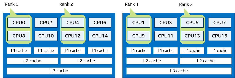
Figure 10 Scatter Order Example
Spread order:
I_MPI_PIN_DOMAIN=2 I_MPI_PIN_ORDER=spread
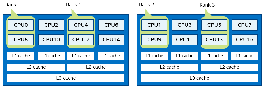
Figure 11 Spread Order Example
Bunch order:
I_MPI_PIN_DOMAIN=2 I_MPI_PIN_ORDER=bunch
Figure 12 Bunch Order Example