A Step-by-Step Case Study Porting a C and MPI Application to DPC++
Graham McKenzie, systems field application engineer, Intel Corporation
@IntelDevTools
Get the Latest on All Things CODE
Sign Up
This article was originally published in The Parallel Universe* magazine back in January 2021. Though oneAPI technology is now focused on the SYCL* framework, the DPC++ references in this article were correct at the time of publication and the content in this article remains relevant.
The heat equation is a problem commonly used in parallel computing tutorials. Let's start from one such exercise published by the Partnership for Advanced Computing in Europe (PRACE). The original code1 describes a C and message passing interface (MPI) implementation of a 2D heat equation, discretized into a single-point stencil (Figure 1). The 2D plane is divided into cells with each cell being updatesid every timestep based on the previous values of itself and its four neighbors. You can find a detailed explanation of the problem on the PRACE repository.2

Figure 1. The 2D heat equation and single-point stencil
The default implementation starts with a 2000 x 2000 cell plane that evolves over 500 steps in time (Figure 2). The plane is initialized to a uniform temperature except for a disc in the center that has a different uniform temperature. External edges are fixed at four different temperatures.
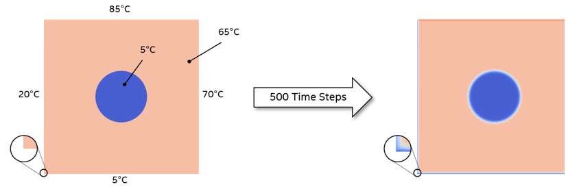
Figure 2. Setting up the computation
This article shows you how to use a code written in standard C/C++, add some simple DPC++ constructs, and run it on different parallel processing units. The article assumes that you are familiar with DPC++, SYCL*, and oneAPI.
Initial Port to DPC++
The original PRACE code features MPI constructs to divide the problem into tiles that are processed across multiple processors and multiple nodes. These are initially removed from the code to focus on the core computation and reintroduced later. Other features, such as regular writing of output images and restart checkpoints is also removed to simplify the problem. The code associated with writing images to depict the initial and final planes is kept as a useful functional verification tool.
A further simplification included updating the whole plane in a single kernel. The MPI-based code separates the edges and interior so that the interior can be updated while the halo is copied from other processes. The edge from one tile becomes the halo from a neighboring tile. After the halo is updated, the edges can be computed, which are dependent upon both the halo and the interior (Figure 3). In this initial port, the edges and interior are treated as one.

Figure 3. Data layout and exchange
DPC++ Headers and Namespace
To use DPC++, you need to include two header files. The first file provides support for the DPC++ framework, is provided with the DPC++ compiler, and is referenced in main.c, core.c, and heat.h. The second header file is taken from the collection of DPC++ sample programs3 and is included for the exception handler. This header file is only referenced from main.c. Also declare the SYCL namespace to simplify SYCL constructs in the code body.

Other changes to main.c involve the main time iteration loop, which is wrapped top and tail with SYCL compatible code. The following five code segments represent contiguous code, but are separated here to aid the description.
Device and Queue
A default selector is chosen, which means that the runtime selects the target device to run the kernel on. This results in use of a GPU, if present, otherwise the host CPU is used. To force a certain device, use cpu_selector or gpu_selector instead of default_selector. A queue is then defined based on the selector and an exception handler, which is wrapped in a try-catch block.

Buffers
Buffers provide containers for data that is present on the target device and are familiar to OpenCL™ code programmers. Take the size of the problem from the data structure found in the original code, and add two to each dimension for the halo (one cell on each side, see Figure 3). Declare global_range as a one-dimensional range based on the problem size and dimensionality of the original host array. The buffers are then defined, referencing this range and pointers to the host data.

Queue Submission and Accessors
The time evolution for-loop is unmodified from the original code. For each iteration of the loop, make a queue submission based on the defined queue. Accessors define how the buffers can be accessed on the device. In this case, declare read_write access for both of the buffers. Although only one buffer is read from and one is written to during each loop iteration, swap the buffers while they remain in context so that they cannot be declared as read or write.

Kernel Execution
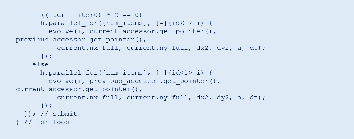
Use a parallel_for kernel, which means the body of this section will be submitted for every item in this problem (that is, every cell in the plane, including the halo in this case). A one-dimensional ID is defined that is passed to the kernel identifying the cell being calculated. You can use a two-dimensional ID, which aids indexing within the kernel body. However, this example opts for a one-dimensional ID to show a functional port with minimal code changes. The body of the kernel is contained within the function evolve in a separate file, core.c, which is described later. The original code has one call point to the equivalent evolve function and then swaps the pointers within the loop. This example alternates pointers to the accessors on each loop iteration via separate parallel_for calls to make buffer management simpler.
Error Handling
Any errors that occur during kernel execution are passed to the host application scope and are handled there with conventional C++ exception handling techniques. In this case, rely on the standard exception handler that is provided in the sample programs.

Kernel Code
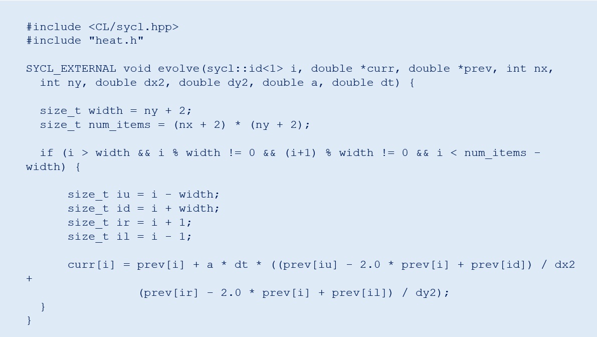
The following code depicts the complete listing for core.c. It is simplified from the original code since the interprocess communication or separating the interior from the edge calculation is not a concern. In the original code, like traditional CPU programming, the evolve function is called once for the entire plane and two nested for-loops traverse the x and y dimensions, calculating the update for each cell. Due to the use of the parallel_for call, the next function is called for each individual cell. Therefore, there are no for-loops.
The global range that is used when calling the parallel_for function includes the halo. It is not updated but is needed to calculate the new values for the edges. The if statement is used to omit the halo so that you do not attempt to read memory outside of the buffers, which would result in a segmentation fault. The actual calculation is confined to the last line of code and is similar to the original code. Various intermediate variables are declared purely to aid readability.
There is a subtle change to the function parameters. The most obvious is the inclusion of the ID, which is needed to identify which cell is being calculated. Also pass in dx2 and dy2 to the kernel rather than dx and dy.dx2. dy2 was originally calculated with the kernel, but its values remain constant across all cells. Since the new evolve function is called for every cell, it is unnecessary to calculate these values each time. You also need to declare the function as SYCL_EXTERNAL to tell the compiler that this is kernel code, which is not obvious from the body. The function prototype in the header file is also modified accordingly.
Compiling the Application and Kernel
The original code uses the mpicc compiler wrapper. To compile for DPC++, use the dpcpp compiler and modify the Makefile accordingly. However, the files associated with writing out PNG files require a C compiler. So, use GNU Compiler Collection (GCC*) for this and wrap the function prototype with extern “C” {…}. These files reference libpng4, which can be installed with sudo apt-get install libpng-dev or downloaded and built from source.
Targeting FPGA
The previous code and modified Makefile are appropriate to target CPU and GPU. For FPGA, make minor changes in the source code and the Makefile.
main.c is modified to select the fpga_selector when FPGA is defined.

For the Makefile, there are extra flags for the compiler and linker. Change the executable name so that it remains separate from the CPU and GPU version.

Running the Application on the Intel® DevCloud
The Intel® DevCloud5 gives users the opportunity to try oneAPI and DPC++ for free with a preinstalled environment and access to multiple Intel® CPU, GPU, and FPGA technologies. The following code assumes that access to Intel DevCloud is already available and configured as per the Get Started Guide.6
Before compiling and running code, install libpng. Since sudo access is not available on the Intel DevCloud, do this by compiling from the source. Download the source code from Reference7 and copy it to the Intel DevCloud, then perform the following steps.

Then, add the following code to ~/.bashrc, or run these commands upon any new session. The environment variable LIBPNG_ROOT can then be used to reference the library in the Makefile:

To compile and run the heat equation, use interactive sessions on the relevant compute nodes for CPU and GPU using one of the following commands, respectively.

Then, make and run the code before exiting the session.

FPGA can take a long time to compile, hence it is best to submit this as a batch job, targeting one of the FPGA compile nodes as follows.

It is also advisable to make clean between CPU and GPU compiles, and FPGA, or compile in a separate directory to avoid conflicts. The contents of compile_fpga.sh are as follows. The file must be executable.

Note that this example keeps a separate Makefile for the FPGA compilation. The status of the job can be checked using the qstat command. Once completed and successful, the kernel can be run on the FPGA using an interactive session, which is launched as follows.

Functional Verification
At the end of the run, the host application prints the final value of a specific cell to the terminal as well as delivers a PNG image of the final plane (Figure 4). The specific value provides a quick check against different code iterations and kernel targets. This value is the same across runs on CPU, GPU, and FPGA and matches the value of the original code. The PNG image can be compared using third-party applications and shows no differences across the three technologies or the original code.
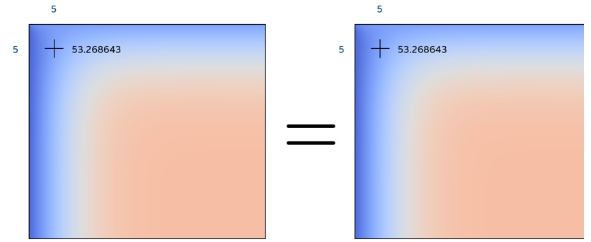
Figure 4. PNG image of the final plane
MPI Implementation
Before adding the MPI multiprocess support back into the code, you must find how to divide the problem between host and device, as well as how to parallelize the operations. A reasonable starting point is to let the host deal with the edge calculations and transfer between processes, and let the device calculate the interior. This also aligns with the approach in the original code. During the time iteration loop, the interior can be evolved independently of the edges with a synchronization point prior to the swapping of pointers at the end of each iteration (Figure 5). The two rows can operate in parallel.
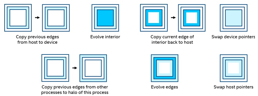
Figure 5. Swapping of pointers
Another important consideration is how the problem is decomposed among MPI processes. The original code uses a two-dimensional decomposition, which means with four processes, the problem is divided into four quadrants (2 x 2 tiles). The data transfers between the host and device is complex and comprises many individual PCIe* transactions for the left and right edges, if you transfer only the data needed. It would be more efficient to transfer the whole data planes back and forth between each iteration of the interior evolution on the device. This is because one large transfer is faster than many small transfers. However, a better way is to decompose the problem in one dimension only. This way, you can transfer only the data needed between the host and device, and those transfers require only two lots of contiguous memory (top and bottom edges, see Figure 6). Figure 7 shows the relative execution time normalized to the time taken to transfer all data. There is no need to transfer left and right edges for the one-dimensional implementation because the global edges of this problem are fixed. So the amount of data transferred for 1D and 2D decompositions is the same.
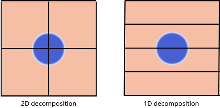
Figure 6. 1D versus 2D data decomposition
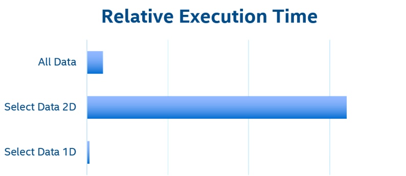
Figure 7. Relative execution time
You can force a one-dimensional decomposition by changing the dimensions passed to the MPI_Dims_create function in setup.c. A zero passed to this function allows the runtime to define the range of each dimension. By using a one as the second value, it forces a single-column implementation.

The buffer implementation used in the previous implementation transfers data to the device implicitly prior to execution and then back again when the buffers go out of context. To be able to transfer data back and forth within the loop, you need finer control. The Unified Shared Memory (USM) model allows data to be allocated as device, host, or shared, and enables familiar C++ constructs to interact with memory. You can use device allocated memory, which enables explicit control over data transfers between the host and device.
Taking the original code as the starting point and keeping all the MPI code, the following changes are made. The header and namespace changes are omitted here, since they are the same as before. The following five sections represent contiguous code.
Device Memory Allocation
The device selector and queue are as per the first implementation. Instead of using buffers, use malloc_device to explicitly define memory on the device, which is then copied over with explicit memcpy functions. The queue needs to be referenced to provide the device context. The wait function waits for the previous memory operations to complete. This is necessary because host execution continues after submitting the requested action to allow parallel operation between host and accelerator. The wait function serves as a synchronization point to ensure that all actions in the queue, which may execute out of order, are complete before host execution continues. In the previous example, the SYCL runtime managed the scheduling operations using buffers.

Copy Edges to Device
At the beginning of each timestep, the top and bottom edges of each slice are copied from host to device using pointer math to identify the edges. These are one row below and above the top and bottom, respectively, due to the halo. First the copy operation is initiated, followed with the exchange function, and the wait function. This is so that the copy and exchange can operate in parallel.

Kernel Execution
In this implementation, the device evolves the interior rather than the whole plane. So, the function name for the compute is changed accordingly. The other subtle difference is that the device memory pointers are passed in instead of the pointers to buffer accessors. The exchange_finalize function is from the original code, which waits for the MPI-based data exchange to complete before evolving the edges. Wait for the kernel to complete before copying the edge of the interior back to the host.

Pointer Swap
The final step for each time iteration is to swap the pointers. On the host, it is handled by the swap_fields function from the original code. For the device, perform a simple pointer swap.

Completion
To finalize the kernel operation, copy both planes back to the host, free the previously allocated device memory, and catch any exceptions that may have occurred.

Kernel Code
Kernel code looks similar to the previous implementation. The only difference is in the if statement. It now excludes both the halo and edges from the top and bottom, but only the halo from the left and right edges.

Additional Changes
Since the left and right edges are now evolved using the device kernel, you need to remove this operation from the host CPU in the evolve_edges function. This function comprises four for-loops, one for each edge. The left and right edges are the last two, which we comment out.
Compiling and Running with MPI
Use the Intel® oneAPI DPC++/C++ Compiler but add additional flags to include and link in the Intel® MPI Library.

To run the code, use mpirun and pass in the number of processes and the executable.

Both the single-point value and PNG comparisons confirm that this implementation functionally matches the previous implementation and the original code. This remains true when run on a single node with multiple processes and across multiple nodes using multiple GPUs.
Conclusion
With a few basic changes to the code, a standard problem is converted to a DPC++ implementation using buffers and accessors. Use the Intel DevCloud to compile code and run on multiple targets including CPU, GPU, and FPGA, with each of those targets producing the same functional results as the original implementation. Finally, use USM to provide explicit control of memory transfers between the host and device necessary to manage the data flow between multiple processes using MPI.
References
- PRACE MPI Implementation of Two-Dimensional Heat Equation Using MPI and C
- PRACE Description of the Two-Dimensional Heat Equation
- oneAPI Direct Programming Samples
- libpng
- Intel DevCloud
- Intel DevCloud Get Started Guide
- libpng Source Code
______
You May Also Like
| Intel® oneAPI Base Toolkit Get started with this core set of tools and libraries for developing high-performance, data-centric applications across diverse architectures. Get It Now See All Tools |