1.1. Generating the Design
Use the MIPI CSI-2 IP parameter editor in the Quartus® Prime software to generate the design example.
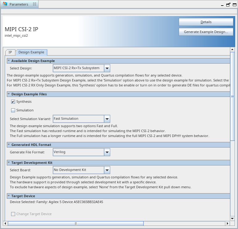
Figure 2. Design Example Tab
- Select Tools > IP Catalog.
The IP parameter editor appears.
- In the IP Catalog, locate and double-click MIPI CSI-2 IP.
- Specify a top-level name for your custom IP variation. The parameter editor saves the IP variation settings in a file named <your_ip>.ip/<your_ip>.qsys.. Click OK.
The IP parameter editor appears.
- In the Design Example tab, turn on Synthesis and/or Simulation to generate the design example.
Note: The MIPI CSI-2 RX-only design does not support simulation.
- If you turn on Simulation, you can select Full simulation or Fast simulation
Full simulation simulates the CSI-2 TX and RX IPs including MIPI D-PHY TX and RX IP in the loopback. Fast simulation bypasses the MIPI D-PHY IP and performs loopback at the PPI between the CSI-2 TX and CSI-2 RX IPs directly. Fast simulation reduces simulation time
- Under Generate File Format, select Verilog or VHDL.
- Under Target Development Kit, No development kit is set by default. The default device OPN is automatically selected based on the target device of the project to match the device on this development kit.
- Click the Generate Example Design button to generate the project files.