Triple-Speed Ethernet IP Design Example User Guide: Agilex™ 3 and Agilex™ 5 FPGAs and SoCs
ID
813899
Date
10/24/2025
Public
1. 10/100/1000 Ethernet MAC Design Example with 1000BASE-X/SGMII 2XTBI PCS with GTS Transceiver
2. 10/100/1000 Multiport Ethernet MAC Design Example with 1000BASE-X/SGMII PCS and Embedded PMA (LVDS)
3. 10/100/1000 Ethernet MAC without Internal FIFO Buffers with 1000BASE-X/SGMII 2XTBI PCS and Embedded PMA Signals (GTS) with IEEE 1588v2
4. 10/100/1000 Ethernet MAC without Internal FIFO Buffers with 1000BASE-X/SGMII TBI PCS and Embedded PMA Signals (LVDS I/O) with IEEE 1588v2
5. Triple-Speed Ethernet IP Design Example User Guide: Agilex™ 3 and Agilex™ 5 FPGAs and SoCs Archives
6. Document Revision History for the Triple-Speed Ethernet IP Design Example User Guide: Agilex™ 3 and Agilex™ 5 FPGAs and SoCs
4.1.2. Generating the Design Example
Figure 28. Procedure to Generate Design Example
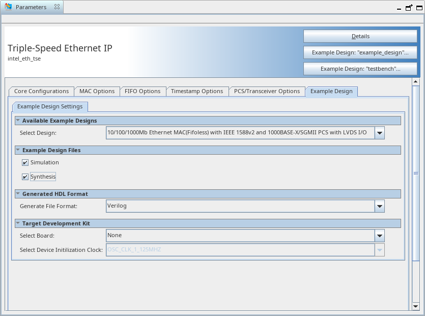
Figure 29. Example Design Tab in the Triple-Speed Ethernet IP Parameter Editor
Follow these steps to generate the hardware design example and testbench:
- In the Quartus® Prime Pro Edition software, click File > New Project Wizard to create a new Quartus Prime project, or File > Open Project to open an existing Quartus Prime project. The wizard prompts you to specify a device.
- Select Agilex™ 3 or Agilex™ 5 device family and select a device for your design.
- Click Finish to close the wizard.
- In the IP Catalog, locate and select Interface Protocol > Ethernet > 1G Multi-rate Ethernet > Triple-Speed Ethernet IP. The New IP Variation window appears.
- Specify a top-level name <your_ip> for your custom IP variation. The parameter editor saves the IP variation settings in a file named <your_ip>.ip.
- Click OK. The parameter editors appears.
- To generate a design example, select a Multi channel Triple Speed Ethernet MAC PCS Example Design (LVDS) with 1588 ( Agilex™ 5, Agilex™ 3) preset from the Presets library and click Apply. When you select a design, the system automatically populates the IP parameters for the design. The parameter editor automatically sets the parameters required to generate the design example.
- To generate a single channel design, navigate to the Core Configuration tab in the parameter editor and set the Number of Ports to 1.
- To generate a multi channel design, navigate to the Core Configuration tab in the parameter editor and set the Number of Ports to 4 (default).
- For Example Design Files, select the Simulation option to generate the testbench, or the Synthesis option to generate the hardware design example.
Note: You must select at least one of the options to generate the design example.
- On the Example Design tab, under Generated HDL Format, select Verilog or VHDL.
Note: If you select VHDL, you must simulate the testbench with a mixed language simulator. The device under test is a VHDL model, but the main testbench file is a System Verilog file.
- Under Target Development Kit, select None.
- Click the Example Design: “example_design” button. The Select Example Design Directory window appears.
- If you want to modify the design example directory path or name from the defaults displayed (intel_eth_tse_0_example_design), browse to the new path and type the new design example directory name (<design_example_dir>).
Note: You must perform the parameter settings based on the steps above to generate the design example.
- Click OK.