3. Parameters
You can select the F-Tile PMA/FEC Direct PHY Multirate Intel FPGA IP core for Intel® Agilex™ 7 devices from the Intel® Quartus® Prime Pro Edition software IP catalog. To customize the IP core, specify the parameters in the IP parameter editor.
The following figures and tables list and describe all the IP parameters and how they appear in the GUI.
Figure 1. IP Parameter Editor: General Tab
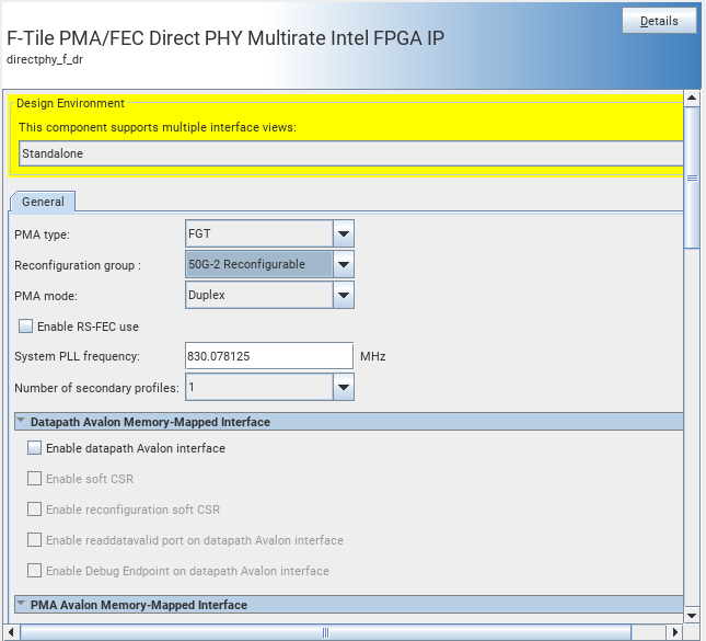
| Parameter | Supported Values | Default Setting | Description |
|---|---|---|---|
| General Options | |||
| PMA type | FGT FHT |
FGT | Selects the targeted PMA type in the F-Tile.
|
| Reconfiguration group | FGT supported values: 25G-1 Reconfigurable 50G-1 Reconfigurable 50G-2 Reconfigurable 100G-2 Reconfigurable 100G-4 Reconfigurable 200G-4 Reconfigurable 200G-8 Reconfigurable 400G-8 Reconfigurable 150G-6 Reconfigurable 300G-12 Reconfigurable FHT supported values: 25G-1 Reconfigurable 50G-1 Reconfigurable 50G-2 Reconfigurable 100G-1 Reconfigurable 100G-2 Reconfigurable 100G-4 Reconfigurable 200G-2 Reconfigurable 200G-4 Reconfigurable 400G-4 Reconfigurable |
25G-1 Reconfigurable | Selects the reconfiguration group. The reconfiguration group indicates the maximum supported fracture types, and data rates along with the maximum count of PMA used within the group. |
| PMA Mode | Duplex TX Simplex RX Simplex |
Duplex | Selects the PMA operation mode. |
| Enable RS-FEC use | On Off |
Off | Select if RS-FEC is enabled in any one of the subsequent profiles. If this attribute is not selected all RS-FEC related attributes in all profiles are grayed out for all profiles. |
| System PLL frequency | 31.25MHz - 1000MHz |
830.078125 | Sets system PLL output clock frequency. |
| Number of secondary profiles | 1-32 | 1 | Selects the number for the secondary profiles. Each secondary profile enables a new tab in the IP GUI. For example, setting value of profiles to 8 generates eight secondary profile tabs. |
| Datapath Avalon® Memory-Mapped Interface Options | |||
| Enable datapath Avalon® interface | On Off |
Off | Enables or disables datapath Avalon® interface. |
| Enable soft CSR | On Off |
Off | Turns the soft CSR feature on or off. |
| Enable reconfiguration soft CSR | On Off |
Off | Turns the reconfiguration soft CSR feature on or off. |
| Enable readdatavalid port on datapath Avalon® interface | Off On |
Off | Off specifies no readdatavalid port, and waitrequest low indicates data valid. On specifies readdatavalid port indicates data valid. |
| Enable Debug Endpoint on datapath Avalon® interface | On Off |
Off | When enabled, IP includes an embedded Debug Master Endpoint that connects internally Avalon® memory-mapped slave interface. The Debug Master Endpoint can access the reconfiguration space of the FEC. It can perform certain test and debug functions via JTAG using System Console. This option may require you to include a jtag_debug link in the system. |
| PMA Avalon® Memory-Mapped Interface Options | |||
| Enable PMA Avalon® interface | On Off |
Off | Enables or disables PMA Avalon® interface. |
| Enable readdatavalid port on PMA Avalon® interface | On Off |
Off | Off specifies no readdatavalid port, and waitrequest low indicates data valid. On specifies readdatavalid port indicates data valid. |
| Enable Debug Endpoint on PMA Avalon® interface | On Off |
Off | When enabled, IP includes an embedded Native PHY Debug Master Endpoint that connects internally to the Avalon memory-mapped slave interface. The Native PHY Debug Master Endpoint can access the reconfiguration space of the PMA lane. |
Figure 2. IP Parameter Editor: Profile #0
| Parameter | Supported Values | Default Setting | Description |
|---|---|---|---|
| Target fracture | All 0-32 |
All | A profile can define a portion of the reconfiguration subset, for example in 100G reconfiguration group, one of the 50G subsets could be defined by this profile. When All is selected this profile is instantiated multiple times and is targeted to all PMAs. Otherwise it is be applied to selected PMA. For multi-PMA profiles, the profile is applied to PMAs consecutively starting from base profile. |
| Profile group id | 0:32 | 0 | The setting should be allocated to each profile configuration based on total number of available sub-set profiles and what id you choose to assign to each profile. |
| Use profile for startup | On Off |
N/A | When enabled, this profile becomes part of start-up configuration.. |
| FGT PMA Configuration rules | Basic OTN CPRI GPON SDI SONET SATA |
Basic | Selects the protocol configuration rules for the FGT PMA. Parameter needs to be set for individual PMAs. |
| PMA Modulation type | NRZ PAM4 |
PAM4 |
Specifies the modulation type used for serial data. |
| PMA Data Rate |
FHT
FGT
|
26562.5 |
Specifies the PMA data rate in units of Mbps. |
| PMA Width | 8 10 16 20 32 64 128 |
32 | Specifies the PMA data width. |
Figure 3. IP Parameter Editor: Secondary Profiles #1-32
| Parameter | Supported Values | Default Setting | Description |
|---|---|---|---|
| Copy from reference profile to profileN | N/A | N/A | When you click this button, the parameter settings of the Reference profile are copied to current profile. |
| Enable separate reference clock ports for profile
Note: This parameter is available only for secondary profiles.
|
N/A | N/A | By default only the reference clock ports for base profile are available at top level. All other PMAs gets the same reference clocks as the base profile. When this option is selected, reference clock ports are available for secondary profiles. When you have different reference clock connections for the same PMAs in different profiles, Intel® Quartus® Prime Pro Edition software detects the intent for reference clock switching. |
Figure 4. IP Parameter Editor: TX FGT Datapath Options P0
| Parameter | Supported Values | Default Setting | Description |
|---|---|---|---|
| TX FGT PMA PN (N=0-32) | |||
| Enable Gray Coding | On Off |
Off | Enables Gray coding. Applicable for PAM4 encoding only. |
| Enable precoding | On Off |
Off | Enables precoding. Applicable to PAM4 encoding only. |
| Enable fgt_tx_beacon port | On Off |
Off | Enable fgt_tx_beacon port for SATA. |
| TX User Clock Setting PN (N=0-32) | |||
| Enable TX user clock 1 | On Off |
Off | Controls the buffer to enable/disable TX user clock 1. If the clock is not used you can disable setting to save power. |
| Enable TX user clock 2 | On Off |
Off | Controls the buffer to enable/disable TX user clock 2. If the clock is not used you can disable setting to save power. |
| TX user clk div by | 12-139.5 |
32 | Division factor from Fvco of TX PLL to TX user clock. Values from 12 to 139.5 are acceptable in 0.5 increments. This clock source drives both TX user clock 1 and 2 |
| TX FGT PLL Settings PN (N=0-32) | |||
| Output frequency | Output | Displays preset frequency | Shows the calculated TX FGT PLL output frequency. |
| VCO frequency | Output | Displays preset frequency | Shows the calculated TX FGT PLL VCO output frequency. |
| Enable TX FGT PLL cascade mode | On Off |
Off | In single lane configurations, selects the mode where RX CDR PLL gets its reference clock from TX PLL output. In multi-lane configurations, selects the mode where RX CDR PLL of initiators and responders get their reference clock from initiator TX PLL output and TX PLL of responders get their reference clocks from initiator TX PLL output. |
| Enable TX FGT PLL fractional mode | On Off |
Off | Enables TX FGT PLL’s fractional mode. |
| TX FGT PLL reference clock frequency | 25 to 380 MHz | 156.25 MHz | Selects the reference clock frequency (MHz) for the TX FGT PLL. Range is:
|
| TX PMA Interface P0
Note: These interface ports are only available in the base profile (Profile #0) tab.
|
|||
| Enable tx_pmaif_fifo_empty port | On Off |
Off | Enables the port which indicates TX PMA Interface FIFO's empty condition. |
| Enable tx_pmaif_fifo_pempty port | On Off |
Off | Enable the port which indicates TX PMA Interface FIFO's partially empty condition. |
| Enable tx_pmaif_fifo_pfull port | On Off |
Off | Enables the port which indicates TX PMA Interface FIFO's partially full condition. |
| TX Core Interface PN (N=0-32) | |||
| TX Clock Options PN (N=0-32) | |||
| Selected tx_clkout clock source | Word Clock Bond Clock User Clock 1 User Clock 2 Sys PLL clock Sys PLL Clock Div2 |
Sys PLL Clock Div2 | Specifies the tx_clkout output port source. |
| Frequency of tx_clkout | Output | Displays frequency value | Displays the frequency of tx_clkout in MHz based on tx_clkout source selection |
| Enable tx_clkout2 port
Note: This parameter is available only in the base profile (Profile #0) as it is related to port selection.
|
On Off |
Off | Enables the optional tx_clkout2 output clock. |
| Selected tx_clkout2 clock source | Word Clock Bond Clock User Clock 1 User Clock 2 Sys PLL clock Sys PLL Clock Div2 |
Word Clock | Specifies the tx_clkout2 output port source. |
| tx_clkout2 clock divby | 1 2 4 |
1 | Selects the tx_clkout2 divider setting that divides the tx_clkout2 output port source. |
| Frequency of tx_clkout2 | Output | Displays frequency value | Displays the frequency of tx_clkout2 in MHz based on tx_clkout2 source selection and tx_clkout2 clock divide by factor. |
Figure 5. IP Parameter Editor: TX FHT Datapath Options P0
| Parameter | Supported Values | Default Setting | Description |
|---|---|---|---|
| TX FHT PMA PN (N=0-32) | |||
| Enable FHT TX P&N Invert | Disabled/Enabled | Disabled | Enable this to invert TX P and N output. |
| Select FHT Lane PLL refclk source | REF_TO_GND, CDR_PLL_CLK, PLL_100_MHZ, PLL_156_MHZ | REF_TO_GND | Selects the FHT Lane PLL refclk source.
|
| FHT user clk div33_34 select | DIV_33 DIV_34 DIV_33_BY_2 DIV_34_BY_2 |
DIV_33_BY_2 |
Selects one of the four DIV clock output for the TX user clock. Refer to Clocking for more details on how to use this output. |
| Enable FHT TX pre-encoder | On Off |
Off | Enables FHT TX pre-encoder. This setting must match the link partner's RX pre-encoder setting. |
| Enable FHT PLL pre-divider | On Off |
Off | Enables FHT PLL pre-divider. If disabled, pre-divider value is 1 and if enabled pre-divider value is 2. In certain configurations, where disabling this sets the lane PLL to fractional mode, you must enable this to set the lane PLL in integer mode for better performance. |
| Enable FHT TX user clk1 | On Off |
Off | Enables the FHT TX user clk1. |
| FHT TX user clk1 select | DIV3334 DIV40 |
DIV3334 | FHT TX user clk1 select, you can select DIV3334 (one of the four DIV clocks listed in user div33_34) or DIV40 clock. Refer to Clocking for more information. |
| Enable FHT TX user clk2 | On Off |
Off | Enables FHT TX user clk2. |
| FHT TX user clk2 select | DIV3334 DIV40 |
DIV3334 | FHT TX user clk2 select, you can select DIV3334 or DIV40 clock. Default value is . Refer to Clocking for more information. |
Figure 6. IP Parameter Editor: RX FGT Datapath Options P0
| Parameter | Supported Values | Default Setting | Description |
|---|---|---|---|
| RX FGT PMA PN (N=0-32) | |||
| Enable Gray Coding | On Off |
Off | Enables Gray coding. Applicable for PAM4 encoding only. |
| Enable precoding | On Off |
Off | Enables precoding. Applicable to PAM4 encoding only. |
| Enable SATA squelch detection | On Off |
Off | Enables squelch detection for SATA. |
| Enable fgt_rx_signal_detect port | On Off |
Off | Enables the fgt_rx_signal_detect port. |
| Enable fgt_rx_signal_detect_lfps port | On Off |
Off | Enables the fgt_rx_signal_detect_lfps port. |
| RX FGT CDR Settings PN (N=0-32) | |||
| Output frequency | N/A | Displays preset frequency | Specifies the non editable RX FGT CDR output frequency initial value derived from the IP configuration. |
| VCO frequency | N/A | Displays preset frequency | Specifies the non editable RX FGT CDR VCO output frequency initial value derived from the IP configuration. |
| RX FGT CDR reference clock frequency | 25.781250-250.000000 | 156.25 MHz | Selects the reference clock frequency for the CDR. |
| Enable fgt_rx_set_locktoref port | On Off |
Off | Asserting this signal keeps CDR in lock to reference mode. Deasserting this signal keeps CDR in auto mode. When switching modes, assert reset. In manual reference clock mode, switch the reset controller to ignore locktodata mode through appropriate write to soft CSRs. |
| Enable fgt_rx_cdr_freeze port | On Off |
Off | This port is for GPON to freeze the CDR lock state during non-active time-slots. |
| CDR lock mode | auto manual lock to reference |
auto | When auto is selected, during the user-initiated reset (or power-up) CDR first tries to lock to data if present. By default, loss of lock to data re-triggers the RX PMA reset. When manual lock to reference is selected, fgt_rx_set_locktoref controls the CDR lock behavior. If fgt_rx_set_locktoref is low, CDR operates in auto mode. If fgt_rx_set_locktoref is high CDR operates in lock to reference mode. In manual mode, the reset controller should be configured to ignore the lock to data status through appropriate soft CSR write. |
| RX User Clock Setting PN (N=0-32) | |||
| Enable RX user clock | On Off |
Off | Divider values of RX CDR output frequency. If the clock is not used, you can disable the clock to save power. This clock source drives both RX User Clock 1 and User Clock 2 in the Core Interface. |
| RX user clock div by: | 12-139.5 | 32 | Division factor from Fvco of RX CDR to RX user clock. Values from 12 to 139.5 are acceptable in 0.5 increments. |
| RX PMA Interface P0
Note: These interface ports are only available in the base profile (Profile #0) tab.
|
|||
| Enable rx_pmaif_fifo_empty port | On Off |
Off | Enables the port that indicates RX PMA Interface FIFO's empty condition. |
| Enable rx_pmaif_fifo_pempty port | On Off |
Off | Enable the port that indicates RX PMA Interface FIFO's partially empty condition. |
| Enable rx_pmaif_fifo_pfull port | On Off |
Off | Enables the port that indicates RX PMA Interface FIFO's partially full condition. |
| RX Core Interface PN (N=0-32) | |||
| RX Clock Options PN (N=0-32) | |||
| Selected rx_clkout clock source | Word Clock Bond Clock User Clock 1 User Clock 2 Sys PLL clock Sys PLL Clock Div2 |
Sys PLL Clock Div2 | Specifies the rx_clkout output port source. |
| Frequency of rx_clkout | Output | Displays frequency value | Displays the frequency of rx_clkout in MHz based on rx_clkout source selection |
| Enable rx_clkout2 port
Note: This parameter is available only in the base profile (Profile #0) as it is related to port selection.
|
On Off |
Off | Enables the optional rx_clkout2 output clock. |
| Selected rx_clkout2 clock source | Word Clock Bond clock User clock 1 User clock 2 Sys PLL clock Sys PLL Clock div2 |
Word Clock | Specifies the rx_clkout2 output port source. |
| rx_clkout2 clock divby | 1 2 |
1 | Selects the rx_clkout2 divider setting that divides the rx_clkout2 output port source. |
| Frequency of rx_clkout2 | Output | Displays frequency value | Displays the frequency of rx_clkout2 in MHz based on rx_clkout2 source selection and rx_clkout2 clock divide by factor. |
Figure 7. IP Parameter Editor: RX FHT Datapath Options P0
| Parameter | Supported Values | Default Setting | Description |
|---|---|---|---|
| RX FHT PMA PN (N=0-32) | |||
| Enable FHT RX PAM4 Level Alternative Coding | On Off |
Off | Enable this for RX PAM4 Level Alternative Coding. When disabled, link partner must send gray code set to 0xB4. When enabled, link partner must send gray code set to 0x6C. You must disable this parameter for normal operation or when in internal or external loopback. |
| Enable FHT RX P&N Invert | Disabled/Enabled | Disabled | Enable this to invert RX P and N input. |
| Enable FHT RX data profile | Disabled/Enabled | Enabled | Enable FHT RX data profile to set the threshold for number of 1’s in 1M RX Data bits that determine the quality of RX data. If the number of 1's received is not within the specified min and max threshold, then RX bad status is indicated.
Note: This parameter must be Enabled.
|
| FHT RX user clk div33_34 select | RX_DIV_33 RX_DIV_34 RX_DIV_33_BY_2 RX_DIV_34_BY_2 |
RX_DIV_33_BY_2 | Selects one of the four DIV clock output for the RX user clock. Refer to Clocking for more information. |
| Enable FHT RX pre-encoder | On Off |
Off | Enables FHT TX pre-encoder. This setting must match the link partner's RX pre-encoder setting. |
| Enable FHT RX user clk1 | On Off |
Off | Enables FHT RX user clk1. |
| FHT RX user clk1 select | DIV3334 DIV40 |
DIV3334 | FHT RX user clk1 select. Refer to Clocking for more information. |
| Enable FHT RX user clk2 | On Off |
Off | Enables FHT RX user clk2. |
| FHT RX user clk2 select | DIV3334 DIV40 |
DIV3334 | FHT RX user clk2 select. Refer to Clocking for more information. |
Figure 8. IP Parameter Editor: RS-FEC P0
| Parameter | Supported Values | Default Setting | Description |
|---|---|---|---|
| Enable RS-FEC | On Off |
Off |
Enables the RS-FEC module.
|
| RS-FEC Mode: |
|
IEEE 802.3 RS (528,514) (CL 91) | Specifies the RS-FEC mode for various topologies. |
| Enable RS-FEC data interleave pattern | On Off |
Off | FEC lanes are bit-interleaved on each physical lane. When enabled: 64/80 (only for IEEE 802). |
Note: The F-Tile PMA/FEC Direct PHY Multirate Intel FPGA IP does not support RS-FEC loopback.
Figure 9. IP Parameter Editor: FGT Analog Parameters PN (N=0-32)
| Parameter | Values | Default Setting | Description |
|---|---|---|---|
| FGT TXEQ Post Tap 1, 1.0 step size | 0 to 19 | 0 | Options for FGT TX EQ Post Tap 1, in 1.0 step size increments. |
| FGT TXEQ Pre Tap 1, 1.0 step size | 0 to 15 | 5 | Options for FGT TX EQ Pre Tap 1, in 1.0 step size increment |
| FGT TXEQ Pre Tap 2, 1.0 step size | 0 to 7 | 0 | Options for FGT TX EQ Pre Tap 2, in 1.0 step size increments. |
| FGT TXEQ Main Tap, 1.0 step size | 0 to 55 | 35 | Options for FGT TX EQ Main Tap, in 1.0 step size increments. |
| Parameter | Values | Default Setting | Description |
|---|---|---|---|
| Select FGT RX Onchip Termination | RX_ONCHIP_TERMINATION_R_1(85 Ohms) RX_ONCHIP_TERMINATION_R_2(100 ohms) |
RX_ONCHIP_TERMINATION_R_1(85 Ohms) | Selects FGT RX termination resistor setting. |
| Enable FGT RX AC Couple | DISABLE ENABLE |
ENABLE | Enable RX external AC coupling setting. |
| Enable FGT VSR mode | VSR_MODE_LOW_LOSS VSR_MODE_HIGH_LOSS VSR_MODE_DISABLE |
VSR_MODE_LOW_LOSS | Enable VSR mode setting. |
| RXEQ VGA Gain | 0 to 63 | 0 | Options for RX EQ VGA gain value, in 1.0 step size increments.
Note: This parameter is only available when the Adaptation mode is set to manual in RX Datapath Options.
|
| RXEQ High Frequency Boost | 0 to 63 | 0 | Options for RX EQ high frequency boost value, in 1.0 step size increments.
Note: This parameter is only available when the Adaptation mode is set to manual in RX Datapath Options.
|
| RXEQ DFE Data Tap1 | 0 to 63 | 0 | Options for RX EQ DFE data tap1 value, in 1.0 step size increments.
Note: This parameter is only available when the Adaptation mode is set to manual in RX Datapath Options.
|
Figure 10. IP Parameter Editor: FHT Analog Parameters PN (N=0-32)
| Parameter | Values | Default Setting | Description |
|---|---|---|---|
| Enable FHT TX P&N Invert | Disabled Enabled |
Disabled | Enable FHT TX P and N inversion. |
| Enable FHT TXOUT Tristate | Disabled Enabled |
Disabled | Enable tristate on FHT TX serial outputs. |
| Select FHT TX Termination | TXTERM_OFFSET_P0(90 Ohms) TXTERM_OFFSET_M1(96.8 Ohms) |
TXTERM_OFFSET_P0(90 Ohms) | Selects FHT TX termination resistor setting. |
| Parameter | Values | Default Setting | Description |
|---|---|---|---|
| Post-Cursor 4, 0.25 step size |
-8.0 to +7.75 | 0.0 | FHT post tap 4 coefficients, 0.25 step size. |
| Post-Cursor 3, 0.25 step size | -8.0 to +7.75 | 0.0 | FHT post tap 3 coefficients, 0.25 step size. |
| Post-Cursor 2, 0.25 step size | -8.0 to +7.75 | 0.0 | FHT post tap 2 coefficients, 0.25 step size. |
| Post-Cursor 1, 0.5 step size | -16.0 to +15.5 | 0.0 | FHT post tap coefficient, 0.5 step size. |
| Main-Cursor,0.5 step size | 0.0 to 41.5 | 41.5 | FHT main tap coefficient, 0.5 step size. |
| Pre-Cursor 1,0.5 step size | -16.0 to +15.5 | 0.0 | FHT pre tap 1 coefficient, 0.5 step size. |
| Pre-Cursor 2,0.25 step size | -8.0 to +7.75 | 0.0 | FHT pre tap 2 coefficients, 0.25 step size. |
| Pre-Cursor 3,0.25 step size | -8.0 to +7.75 | 0.0 | FHT pre tap 3 coefficients, 0.25 step size. |
| Parameter | Values | Default Setting | Description |
|---|---|---|---|
| Enable FHT RX P&N Invert | Disabled Enabled |
Disabled | Enable FHT RX P and N inversion. |
| Select FHT RX Termination | RXTERM_OFFSET_P0(90 Ohms) RXTERM_OFFSET_P2(94.6 Ohms) RXTERM_OFFSET_P3(97.7 Ohms) RXTERM_OFFSET_P4(100 Ohms) RXTERM_OFFSET_P5(102.3 Ohms) RXTERM_OFFSET_P6(105.4 Ohms) RXTERM_OFFSET_P7(107.7 Ohms) RXTERM_OFFSET_P8(110 Ohms) RXTERM_OFFSET_M4(80.8 Ohms) RXTERM_OFFSET_M5(83.1 Ohms) RXTERM_OFFSET_M6(85.4 Ohms) RXTERM_OFFSET_M7(87.7 Ohms) |
RXTERM_OFFSET_P0(90 Ohms) | Selects FHT RX termination resistor setting. |
| Select FHT external AC Cap | EXTERNAL_AC_CAP_ENABLE EXTERNAL_AC_CAP_DISABLE |
EXTERNAL_AC_CAP_ENABLE | Enable external AC coupling capacitance. |