AN 964: Signal Tap Tutorial for Intel Agilex® 7 Partial Reconfiguration Designs
ID
710463
Date
10/02/2023
Public
2.1. Step 1: Getting Started
2.2. Step 2: Preparing the Base Revision
2.3. Step 3: Preparing the Implementation Revisions for Debugging
2.4. Step 4: Configuring Signal Tap Logic Analyzer
2.5. Step 5: Generating Programming Files
2.6. Step 6: Programming the FPGA Device
2.7. Step 7: Performing Data Acquisition
2.7. Step 7: Performing Data Acquisition
After loading the appropriate .rbf onto the board, start data acquisition on the Signal Tap logic analyzer.
To perform data acquisition:
- Make sure that the Signal Tap Logic Analyzer loads the .stp file in the current active revision.
- In the top right corner of the Signal Tap window, set up the JTAG connection to the board with the following options:
Option Description Hardware USB-BlasterII Device Intel Agilex® 7 F-Series: AGFB014R24A
Intel Agilex® 7 M-Series: AGMF039R47AR0
Bridge Index 0 Bridge index is set to 0 for tapping signals in the PR region.
Figure 26. JTAG Configuration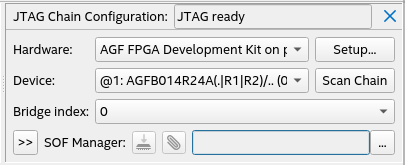
- On the Signal Tap toolbar, click Run Analysis
 .
The analysis may take a few minutes.When the analysis finishes, the Signal Tap Logic Analyzer loads the waveforms to the window.
.
The analysis may take a few minutes.When the analysis finishes, the Signal Tap Logic Analyzer loads the waveforms to the window.
The following section displays the resultant waveforms for all PR configurations.