F-Tile Avalon® Streaming IP for PCI Express* Design Example User Guide
ID
683372
Date
10/20/2025
Public
3.2. Generating the Design Example
Figure 18. Procedure
- In the Quartus® Prime Pro Edition software, create a new project (File > New Project Wizard). Click Next.
- Select the Empty Project type and specify the Directory, Name, and Top-Level Entity. Click Next.
- For Family, Device & Board Settings under Family, select Agilex™ 7 and then select Target device for your design. After that, click Finish to proceed.
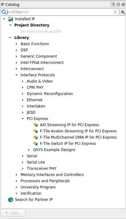
- Select Tools → IP Catalog to open the IP Catalog. Select the F-Tile Avalon® Streaming IP for PCI Express* (Library → Interface Protocols → PCI Express → F-Tile Avalon® Streaming IP for PCI Express* ), then click Add.
- In the New IP Variant dialogue box, specify a top-level name for your new custom IP variant and the directory for it. The IP Parameter Editor saves the IP variant settings in a file named <your_ip>.ip.
- Click Create. The IP Parameter Editor appears as shown in the figure below. The F-Tile Avalon Streaming IP for PCI Express has Top-Level Settings, PCIe0 Settings, Example Designs, and Analog Parameters tabs to allow you to quickly configure your custom IP variant.
- On the Top-Level Settings tabs, specify the parameters for your IP variant.
Note: This design example only supports the default settings in the Parameter Editor of the F-tile Avalon® Streaming IP for PCIe.If you are using the SR-IOV design example, run the following steps to enable SR-IOV:
- At the PCIe Settings → PCIe PCI Express / PCI Capabilities → PCIe Device → PCIe Multifunction and SR-IOV System Settings tab, check the box Enable multiple physical functions and the Enable SR-IOV support option.
- At the PCIe MSI-X tab under the PCIe PCI Express / PCI Capabilities tab, enable the MSI-X feature as required.
- At the PCIe Base Address Registers tab under the PCIe Settings tab, enable BAR0 for both PF and VF.
- Other parameter settings are not supported for this design example.
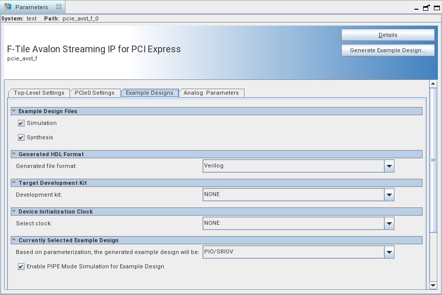
- On the Example Designs tab, make the following selections:
- For Example Design Files, turn on the Simulation and Synthesis options. If you do not need these simulation or synthesis files, leaving the corresponding option(s) turned off significantly reduces the example design generation time.
- For Generated HDL Format, only Verilog is available in the current release.
- For Target Development Kit, select either the Intel Agilex 7 FPGA F-Series Development Kit (Production 1 2x F-Tile), or NONE to target on the device selected for the current Quartus Prime project. If you select the development kit, the VID-related settings including the pin assignments are included in the .qsf file of the generated design example, and you are not required to add them manually. Note that these settings are board-specific.
- For Device Initialization Clock, select OSC_CLK_1_125MHz when the Agilex 7 FPGA F-Series Development Kit (Production 1 2x F-Tile) is selected. Otherwise, the selected frequency must match the frequency you have provided for the device's OSC_CLK_1 pin of your board.
Note: Starting with the Quartus® Prime Pro Edition software version 23.4, the software enforces a check for the appropriate .qsf assignment required to constrain the device’s OSC_CLK_1 pin for projects which contain transceivers in the design. A failure to provide this .qsf assignment causes the compilation to fail.
- For Currently Selected Example Design, select PIO/SRIOV or PERFORMANCE_DESIGN.
- Click on Generate Example Design to generate the design example variant. When the prompt asks you to specify the directory for your design example, you can accept the default directory, /pcie_avst_f_0_example_design, or choose another directory. Then, click OK to kick off the design example generation.
Figure 19. Example Designs Tab
- Click Finish. You may save your .ip file when prompted, but it is not required to be able to use the design example.