In this module, you will learn:
- Steps to set up and configure the Intel® Time Coordinated Computing (Intel® TCC)-supported hardware successfully using best known configurations included in Intel® Board Support Package and Intel® Time Coordinated Computing Mode (Intel® TCC Mode).
- Steps to install and evaluate Intel real-time solution using the laser engraving sample application.
- You can also get access to expert advice in the Intel® TCC Tools forum.
Overview
This sample application demonstrates a proof of concept for Intel’s real-time out-of-box configuration using Intel® Board Support Package and Intel® TCC Mode in achieving consistent workload cycle time and low jitter value.
Before running the sample application, follow the steps in the Get Started with Intel® Time Coordinated Computing Tools (Intel® TCC Tools) 2022.1 for Ubuntu* Host and Yocto Project*, and UEFI BIOS Target to build the Yocto Project*-based image for Intel® Core™ i7-1185GRE processor.
Once the platform is set up, follow step 4 to step 6 below to install the Intel® TCC Tools and other dependencies to run this sample application.
Click on Configure and Download, then scroll down the page to download the sample application.
| Time to complete | 1 hour |
| Programming Language |
Python* 3.7, C++, G-code |
Target System Requirements
- Intel® Core™ i7-1185GRE processor
- Yocto Project image with LTS Real-time Kernel v5.10.65-rt53 and Intel® Board Support Package
- Intel® TCC Tools version 2022.1
- UFACTORY uArm Swift Pro SDK
- Python3.7 with pandas and matplotlib libraries
- Boost
- stress-ng tool
- UFACTORY uArm Swift Pro* robotic arm (optional)
How It Works
Software Architecture
There are multiple software components used in the laser engraving sample application:
- Intel® TCC Mode: A single setting in the BIOS that configures a combination of power management, PCIe* virtual channels settings, Data Direct Input/Output (DDIO) settings and time synchronization settings for the I/O subsystems.
- Yocto Project-based BSP: Contains Linux kernel drivers and PREEMPT_RT patch, compiled with a list of real-time parameters that let users perform task prioritization, interrupt scheduling, and specify CPU core for real-time workload.
- Intel® TCC Tools Measurement Library: Provides a set of API libraries to measure, collect, analyze, and print cycle time and latency data of the real-time workload.
- C++ SDK for uARM: Provides the C++ SDK to communicate with uARM.
- stress-ng tool: To stress the system with non-critical workload
The following diagram shows the software architecture of the platform.

Sample Application Flow
The sample application performs laser engraving as the real-time workload while running the stress-ng tool as best effort workload imitation in the system and as non-real-time workload imitation. The flow starts with CPU core 3 initializing the robotic arm and setting a deadline requirement of 500 ms±20 µs cycle time for each iteration. The CPU then loads the laser engraving commands with coordinates into the memory before initiating the Intel® TCC Tools to begin the cycle time and jitter measurement. Core 3 then reads one line of code from the memory and sends the command to the robotic arm. It then stays idle until the iteration reaches the deadline. CPU core 3 then reads another line of command and sends to the robotic arm before staying idle. The iteration continues until CPU core 3 reaches the end of the file. The following diagram shows the operation flow of the application.
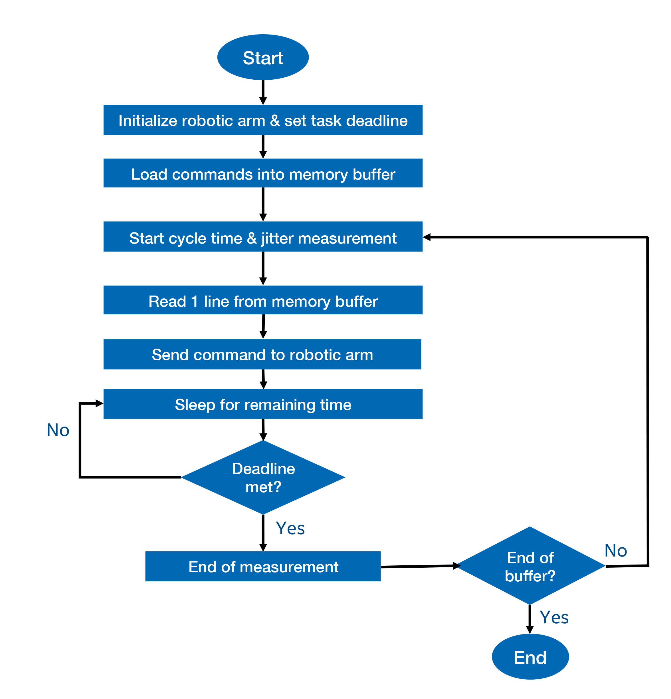
The system measures the cycle time to complete each iteration and the jitter value of processor’s wake up time, using Intel® TCC Tools.

Get Started
Step 1: Prepare and Set up the Host System
- You need to set up a host system to build the Intel® Board Support Package for Yocto Project* and set up Intel® TCC Tools. The following are the minimum host system configurations:
- Intel® Core™ i7 processor (4 cores)
- Linux* OS of choice for the Yocto Project* build is Ubuntu* 16.04 LTS OS or higher. Refer to Yocto Project Quick Start for more information.
- Minimum of 32 GB Random Access Memory (RAM) and 500GB disk space are recommended.
- High-speed network connectivity.
- USB flash drive 64GB minimum (to prepare the bootable Yocto Project*-based image).
- Follow the steps in Section 2.0 of the Yocto Project*-based Board Support Package for 11th Gen Intel® Core™ Processors on IoT Platforms Get Started Guide to start setting up the host system.
Step 2: Getting Started with Intel® Board Support Package
- The sample application uses Kernel 5.10 BSP release (MR5). Follow the steps in Section 3.2 Getting Started with Kernel 5.10 BSP release(MR5) in the Yocto Project*-based Board Support Package for 11th Gen Intel® Core™ Processors on IoT Platforms Get Started Guide to obtain Intel® Board Support Package and preparing to build the Yocto Project*-based image.
- Follow the steps in Option B: Full Image with Real-time (RT) Kernel as Default Boot Image - Mandatory for Intel® TCC Tools in section 3.2.3 Build the Yocto Project*-based Image to build Yocto Project*-based image with PREEMPT_RT kernel.
Step 3: Boot Up 11th Gen Intel® Core™ Processor on Intel® TCC-Supported Hardware
- Follow the steps in Section 4.0 Next Step to Boot Up 11th Gen Intel® Core™ Processor Reference Validation Platform in the Yocto Project*-based Board Support Package for 11th Gen Intel® Core™ Processors on IoT Platforms Get Started Guide to boot up the Intel® TCC-supported hardware with a bootable USB flash drive.
- A boot option menu is shown when the Yocto Project*-based image is installed in the local drive. Choose boot linux-intel-ese-lts-rt-5.10 in the boot option menu to boot up the board with kernel 5.10 with PREEMPT_RT patch.

Step 5: Install Intel® TCC Tools
In this section you will install Intel® TCC Tools on both the host and target systems based on certain steps in Get Started with Intel® Time Coordinated Computing Tools (Intel® TCC Tools) 2022.1 for Ubuntu* Host and Yocto Project* + UEFI BIOS Target.
- Follow the steps in Step 3: Download and Install the Package to download and install Intel® TCC Tools on host system.
Note: Dependencies installation for host machine as specified in Step 4 in the Get Started with Intel® Time Coordinated Computing Tools (Intel® TCC Tools) 2022.1 for Ubuntu* Host and Yocto Project* + UEFI BIOS Target document are optional is optional for this sample application.
- Follow the steps in Step 5: Install on Target to install and setup Intel® TCC Tools on your target machine.
Note: The sample application does not use Data Streams Optimizer and Software SRAM features, therefore the steps after Step 5 in the Get Started with Intel® Time Coordinated Computing Tools (Intel® TCC Tools) 2022.1 for Ubuntu* Host and Yocto Project* + UEFI BIOS Target document are optional.
Step 6: Install Software Dependencies
- On the host machine, click on Configure & Download, then scroll to the bottom of the page, to download the laser engraving sample application.
- Go to the downloaded folder and unzip the downloaded package.
unzip applications.industrial.realtime.demo.robotic-arm-engraving.zip - Go to the sample application folder and run the download_dependencies_host.sh script in the sample application directory to download the following software dependencies:
- uARM SDK
- Boost
- Python3.7
- stress-ng tool
cd applications.industrial.realtime.demo.robotic-arm-engraving chmod +x ./download_dependencies_host.sh ./download_dependencies_host.sh - Once all the downloads have been completed, the terminal will show -------Download completed------ message. The following image shows an example of successful download completion.

Figure 5. Screen showing the system completed downloads for software dependencies - Copy the sample application directory from the host system to the target system using the command below.
cd .. scp -r applications.industrial.realtime.demo.robotic-arm-engraving root@<target_ip_address>:/home/root - On the target system, go to the sample application folder and run the install_dependencies_target.sh script to install the software dependencies.
cd applications.industrial.realtime.demo.robotic-arm-engraving
chmod +x ./install_dependencies_target_sh
./install_dependencies_target.sh
The software dependencies installation process may take about 40 - 50 mins to complete. Do not cancel the installation process to avoid errors when running the sample application.
- Once the installation is completed, the system prints ------Installation completed------- message as shown in the image below.
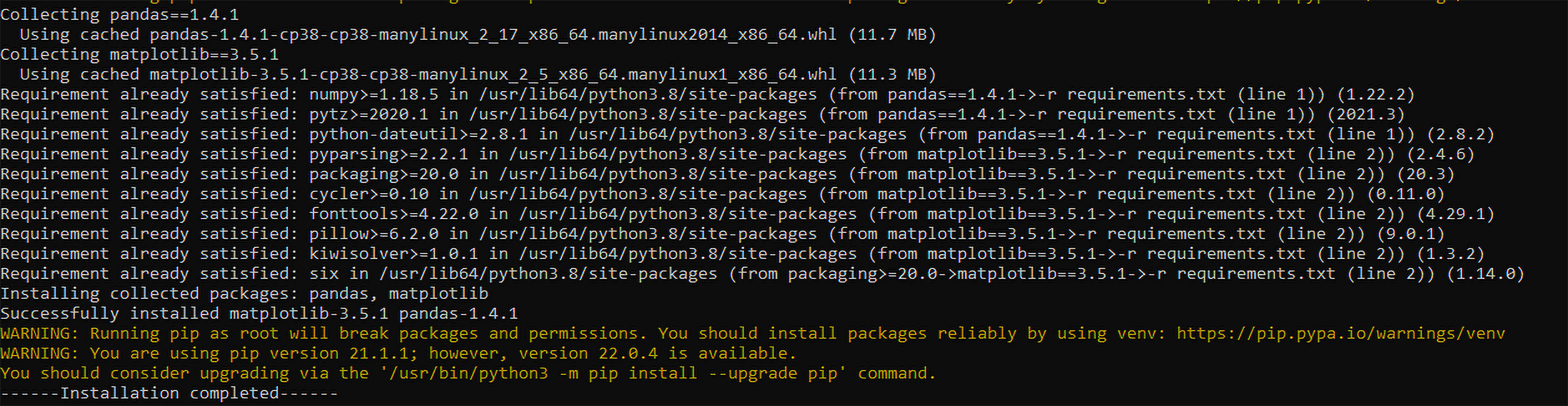
Figure 6. Screen showing software dependencies installation complete
Step 7: Verify System Configuration with Real-Time Readiness Checker
- Before running the application, use the tcc_rt_checker to verify the real-time readiness of the target system. Run the following command in a terminal to check the system configuration.
tcc_rt_checker - If the tool detects a supported processor, it completes all real-time configuration checks and prints the results. The tool identifies if the system has the optimal configurations for real-time applications and highlights the components that are not optimally configured. Ensure the following checkers should show RT_Ready as the result before running the sample application.
- RT kernel checker
- GT COS Checker
- Linux* kernel’s command-line parameters checker
- Enhanced Intel SpeedStep® Technology
- Intel® Speed Shift Technology
- Low Power S0 Idle Capability
- CPU PCI Express* ASPM
- Intel® Hyper-Threading Technology
- Cache Allocation Technology
- Cache Allocation Technology capabilities
- SMI optimization
- #AC Split Lock
The below screenshot is an example of the real-time checker's results.
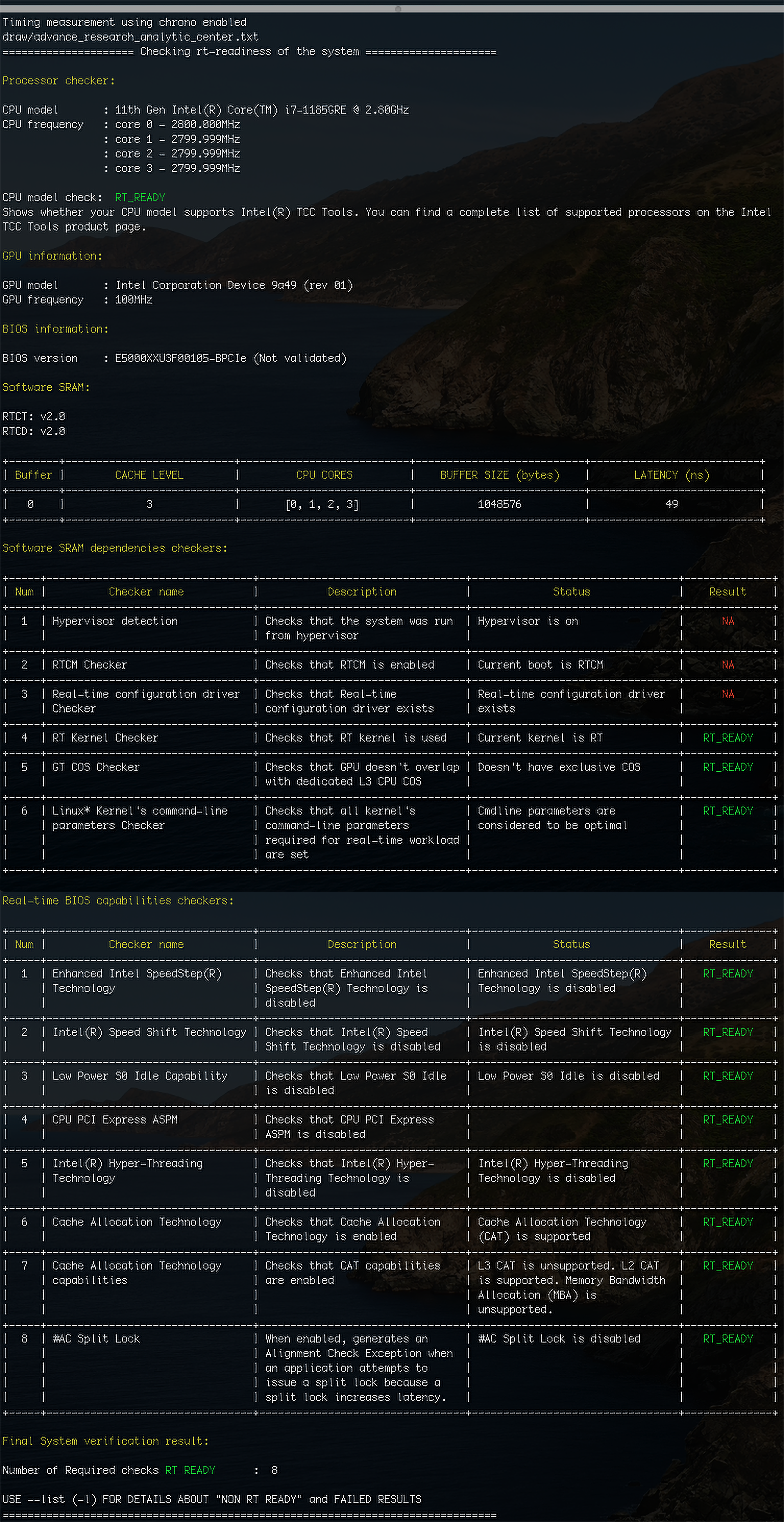
Figure 7. Example of real-time checker tool results
Step 8: Compile and Run the Sample Application
- In the applications.industrial.realtime.demo.robotic-arm-engraving-tcc directory, run the following command to compile the sample application.
make tcc - Convert a gcode file using the following command with input parameter l to convert and save the gcode file in drawing folder.
python3 convert.py -f gcode-input/intellogo.gcode -c l -
The sample application provides some gcode files for evaluation in two different folders: drawing and laser. In this learning path, the sample application is using intellogo.gcode as the gcode input file.
- Specify the library folder for g++ compiler using the below command.
export LD_LIBRARY_PATH=/usr/lib - The sample application requires a serial port name as an input. If you have the robotic arm connected, provide the port name that is connected to the robotic arm. Otherwise, you can select any serial ports that are unoccupied, as an input.
To list all available serial ports, use the following command.ls /dev | grep tty -
Run the sample application using the following command.
chmod +x run.sh
taskset -c 3 ./run.sh draw/intellogo.txt
/dev/<serialport_name>
The command taskset -c 3 is to specify CPU core 3 as the assigned CPU to run the laser engraving workload
-
On a new terminal, initiate the stress-ng test on CPU core 0, 1, and 2.
stress-ng --cpu 1000 --taskset 0-2
Jitter and Cycle Time Measurement Result
At the end of the application, Intel® TCC Tools will display the measurement results on the screen. The measurement results consist of:
- Number of iterations ran
- Average, minimum, and maximum duration calculated based on each iteration
- Minimum, maximum and average jitter value between the thread idle and wake up time
The following figure shows an example of measurement results collected from the sample application.
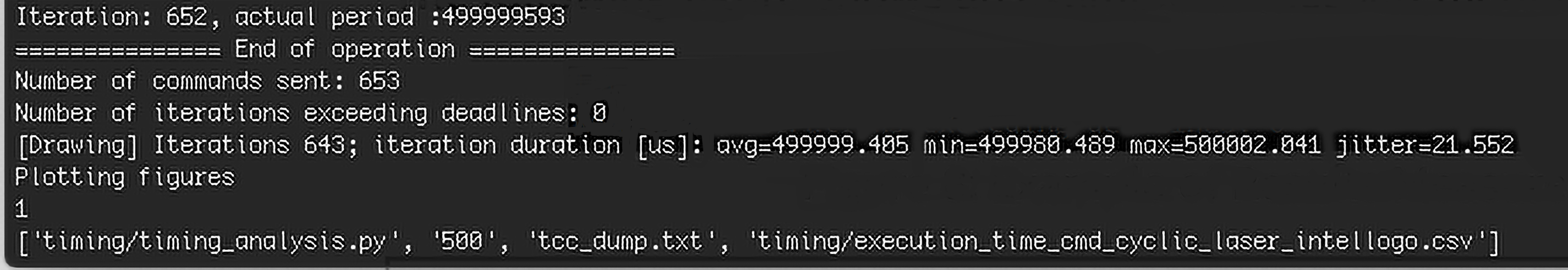
Figure 8. Example of Results Measured from the Sample Application