1. Introduction to Agilex™ 5 FPGA Thermal Design Guidelines
2. Agilex™ 5 FPGA Mechanical Construction
3. Agilex™ 5 FPGA CTM Construction
4. Power and Thermal Calculator (PTC)
5. General FPGA Thermal Design Considerations
6. Design Examples
7. Heat Sinks
8. Document Revision History for the Thermal Design User Guide: Agilex™ 5 FPGAs and SoCs
A. Agilex™ 5 FPGA Product Keys and Package Drawings
2. Agilex™ 5 FPGA Mechanical Construction
Intel Agilex 5 FPGAs are lidless square BGA devices and are offered in various packages. The ball pitch of the variable pitch ball grid array (VPBGA) is variable, ranging from 0.65mm to 1.45mm in a single package, to ease signal routing and use the design rules equivalent to 0.8mm ball pitch packages. The following example figure shows the mechanical drawing for the Agilex™ 5 FPGA, part number A5ED0655B32A.
Figure 1. Agilex™ 5 FPGA, A5ED0655B32A
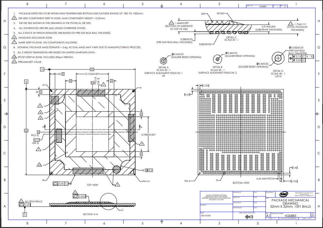
Be aware that there are capacitors (see the die-side component keep in zone as Zone 2 in the above mechanical drawing) on top of the substrate and therefore there are keep-out zones that you should observe to avoid any physical interference for general system packaging and cooling solutions.
Related Information