4.3.1.1. NOP(0x0)
4.3.1.2. get_hssi_profile for E-Tile
4.3.1.3. get_hssi_profile for F-Tile
4.3.1.4. set_hssi_profile for E-Tile
4.3.1.5. set_hssi_profile for F-Tile
4.3.1.6. read_MAC_statistic
4.3.1.7. get_mtu
4.3.1.8. set_csr for E-Tile
4.3.1.9. set_csr for F-Tile
4.3.1.10. get_csr for E-Tile
4.3.1.11. get_csr for F-Tile
4.3.1.12. enable_loopback for E-Tile
4.3.1.13. enable_loopback for F-Tile
4.3.1.14. disable_loopback for E-Tile
4.3.1.15. disable_loopback for F-Tile
4.3.1.16. Reset MAC Statistics
4.3.1.17. set_mtu for F-Tile
4.3.1.18. Ncsi_get_link_status
4.3.1.19. Reserved
4.3.1.20. firmware_version (0xFF)
6.1. Driving Multiple Ports with the Same Clock
6.2. Clock Connections for MAC Asynchronous Client FIFO
6.3. F-Tile Clock Connections for PTP Synchronous and Asynchronous cases
6.4. Clock Connections for SyncE Operation on E-Tile
6.5. Clock Connections for SyncE Operation on F-Tile
6.6. F-Tile PMA and FEC Direct PHY IP Clock Output
7.1.1. Device Feature Header Lo
7.1.2. Device Feature Header Hi
7.1.3. Feature GUID_L
7.1.4. Feature GUID_H
7.1.5. Feature CSR ADDR
7.1.6. Feature CSR Size Group
7.1.7. Version
7.1.8. Feature List
7.1.9. Interface Attribute Port X Parameters
7.1.10. HSSI Command/Status
7.1.11. HSSI Control/Address
7.1.12. HSSI Read Data
7.1.13. HSSI Write Data
7.1.14. HSSI Ethernet Port X Status
7.1.15. Priority Flow Control
7.1.16. Priority Flow Control TX Queue Statistics
7.1.17. Priority Flow Control RX Queue Statistics
7.1.18. Priority Flow Control TX Queue Threshold
7.1.19. Priority Flow Control RX Queue Threshold
7.1.20. F-Tile DR Controller Status
7.1.21. HSSI Hotplug Debug Port Control
7.1.22. HSSI Hotplug Debug Port Status
3.2. E-Tile Port Enablement Guidelines and Restrictions
Ethernet Subsystem Intel FPGA IP for Agilex devices provides up to 16 Ethernet ports. As the IP is implemented based on Intel Agilex E-tile Hard IP for Ethernet Intel FPGA IP Core, the ports are mapped to E-tile transceiver channels and channel placement rules of the Hard IP are also applicable to Subsystem IP. PTP channels are not configurable from the IP GUI.
| Subsystem Port | E-tileTransceiver Channel | EHIP Core |
|---|---|---|
| 0 | 0 | 0 |
| 1 | 1 | 0 |
| 2 | 2 | 0 |
| 3 | 3 | 0 |
| - | PTP Channel (4) | 0 |
| - | PTP Channel (5) | 0 |
| - | PTP Channel (6) | 1 |
| - | PTP Channel (7) | 1 |
| 4 | 8 | 1 |
| 5 | 9 | 1 |
| 6 | 10 | 1 |
| 7 | 11 | 1 |
| 8 | 12 | 2 |
| 9 | 13 | 2 |
| 10 | 14 | 2 |
| 11 | 15 | 2 |
| - | PTP Channel (16) | 2 |
| - | PTP Channel (17) | 2 |
| - | PTP Channel (18) | 3 |
| - | PTP Channel (19) | 3 |
| 12 | 20 | 3 |
| 13 | 21 | 3 |
| 14 | 22 | 3 |
| 15 | 23 | 3 |
General guidelines of Subsystem port configurations:
- Enable the same number of port(s) as specified in NUM_ENABLED_PORTS parameter.
- Click File > Refresh System whenever you modify port configurations to ensure parameter options are displayed correctly.
- 100G CAUI-4 is considered as a single port configuration and can only be enabled on port 0/4/8/12. When any of the four ports are configured as 100G CAUI-4 profile, the remaining three ports in the same EHIP Core is hidden in the IP GUI.
- When configuration of a port matches the configuration of the previous port in the same EHIP Core, this message is displayed at the bottom of the port configuration:
hssi_ss:PORT <n> configuration matches with PORT <n-1> configuration
Figure 2. Matching Ports Configurations
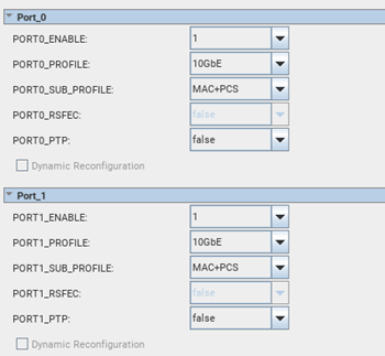
In the IP configuration tab, the parameters are only available to be configured for the first port. Parameters of subsequent matching port(s) are hidden and would match the settings of the first port.
- Like E-tile Hard IP for Ethernet channel placement, the E-tile transceiver requires RS-FEC to be enabled on contiguous ports only.
- For EHIP Core 1 (Port 4/5/6/7) and EHIP Core 3 (Port 12/13/14/15), PTP-enabled multi-port design must be configured in sequence, starting from the first port of the EHIP Core. For example, enable PTP starting from Port 4, followed by Port 5, 6 and 7 for 4-port PTP design on EHIP Core 1.
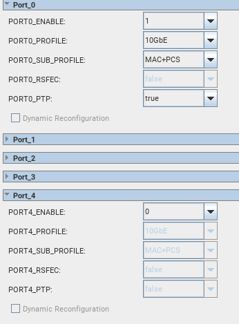
- For EHIP Core 0 (Port 0/1/2/3) and EHIP Core 2 (Port 8/9/10/11), PTP- enabled multi-port design must be configured in reverse sequence, starting from the last port of the EHIP Core. For example, enable PTP starting from Port 3, followed by Port 2, 1 and 0 for 4-port PTP design on EHIP Core 0.
If the expected sequence is not observed for EHIP Core 0 and 2, the IP Core automatically enables the subsequent PTP port(s) to align with E-tile channel placement rules. For example, if Port 0 is enabled with PTP before Ports 3,2,1 is configured, the IP Core automatically enables the Ports 3,2,1 with PTP.
Figure 3. IP Core Automatically Enables the Subsequent PTP Port(s)
Related Information