Quartus® Prime Pro Edition User Guide: Third-party Simulation
1.9.1. Setting Up the Run Simulation Feature
To setup the Run Simulation feature by specifying the settings that identify your simulator, output path, and other options, follow these steps:
- Open a project in the Quartus® Prime software.
- Click Tools > Options > EDA Tool Options and specify the location of your simulator executable file, as Execution Paths for Supported EDA Simulators describes in detail.
Figure 7. Specifying Simulator Install Path
- To enable automated generation of the IP simulation models whenever you generate HDL for IP in Platform Designer, click Tools > Options > Board and IP Settings > IP Simulation. Make sure Generate IP simulation model when generating IP option is turned on.
Figure 8. Specifying Automated IP Simulation Model Generation
- Click Assignments > Settings > EDA Tool Settings > Simulation and specify the following simulation settings in the Simulation pane:
Figure 9. Simulation pane of the EDA Tool Settings dialog
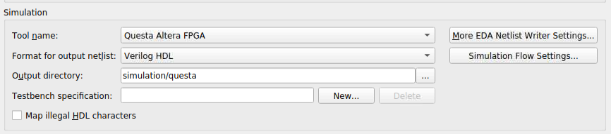
- Set the general simulation settings:
Table 8. Simulation Options (EDA Tool Settings Page) Options Dialog Box Option Allowed Values Description Tool name Specifies the supported simulator to automatically run. Format for output netlist - Verilog HDL
- VHDL
Specifies Verilog or VHDL as the format for the output netlist. The setting does not apply to RTL simulation.
Output directory Any valid path. Specifies the directory to store all output files for simulation. The default path is simulation/<simulator> .
Map illegal HDL characters - Disabled (default)
- Enabled
When enabled, this option directs the EDA Netlist Writer to map illegal characters for VHDL or Verilog HDL. The setting does not apply to RTL simulation.
If you select VHDL for Format for output netlist, the EDA Netlist writer maps non-alphanumeric characters, including brackets ([]), parentheses, (()), angle brackets (<>), and braces ({}) to (_a) in VHDL Output Files. This option generates VHDL 1987 compatible names.
If you select Verilog HDL for Format for output netlist, the EDA Netlist writer maps the vertical bar (|), tilde (~), and colon (:) characters in hierarchical node names to the legal Verilog HDL characters z, x, and underscore (_) in Verilog Output Files. This option also maps other illegal non-alphanumeric characters, including brackets ([]), parentheses, (()), angle brackets (<>), and braces ({}) to underscore (_).
- For Testbench Specification, click New and enter the testbench information, including the Top level module in testbench, Simulation period, and Testbench and simulation files options.
Figure 10. Defining Testbench Specification
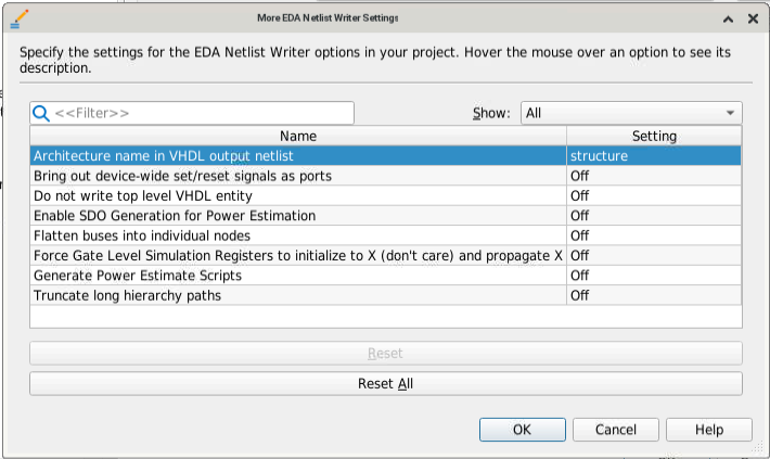
- Click More EDA Netlist Writer Settings to specify settings that control how the Compiler generates and formates the gate-level netlist for gate-level simulation.
Figure 11. More EDA Netlist Writer Settings Dialog Box
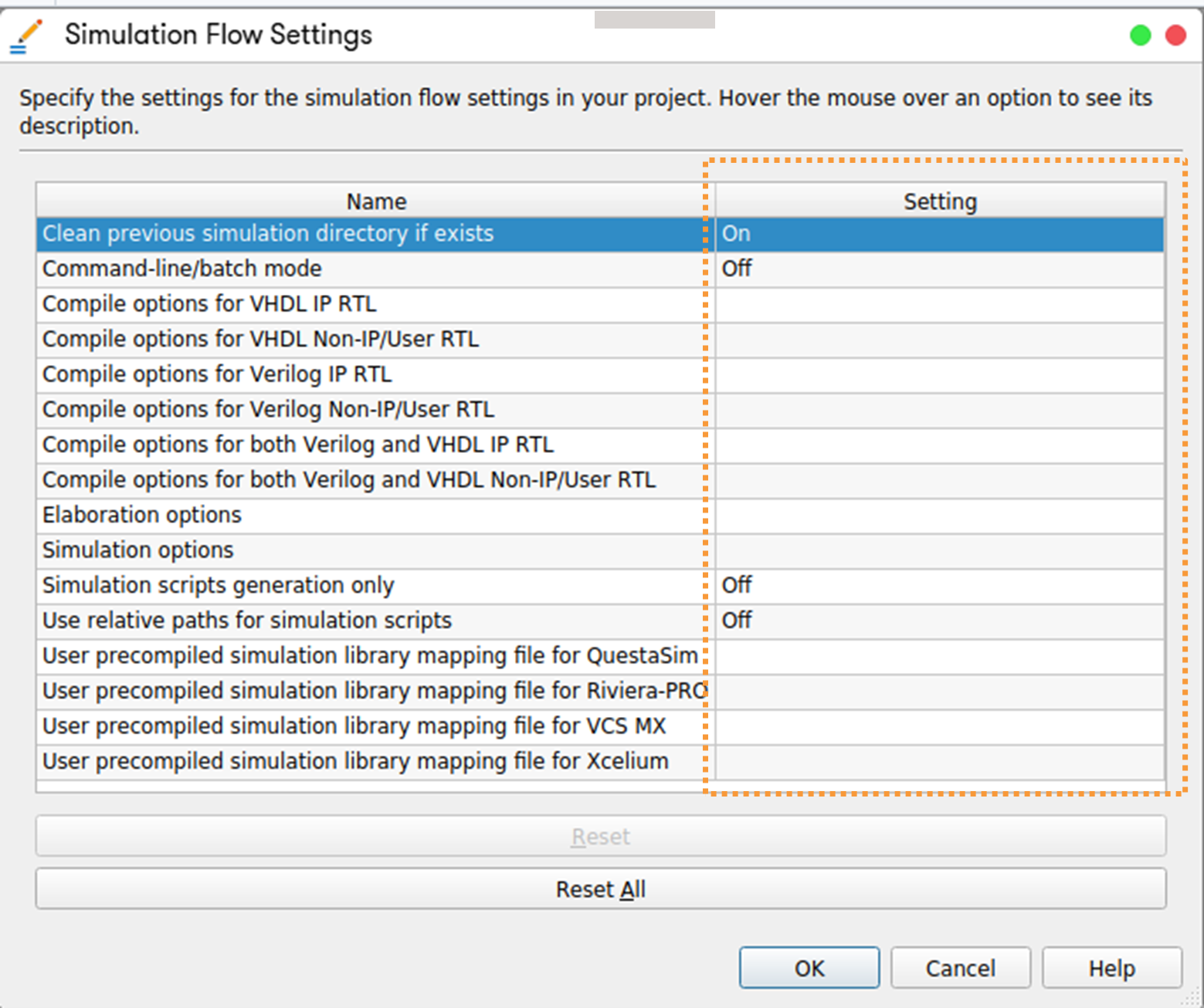
- Click Simulation Flow Settings to specify additional options for the automated simulation flow, as Simulation Flow Settings describes in detail.
Figure 12. Simulation Flow Settings Dialog Box
- Set the general simulation settings:
Section Content
Installation Paths for Supported EDA Simulators (EDA Tool Options Page)
Simulation Flow Settings (EDA Tool Settings Page)
More EDA Netlist Writer Settings (EDA Tool Settings Page)