A newer version of this document is available. Customers should click here to go to the newest version.
2.1.1. Constructing Communication Links in the Link Designer Module
2.1.2. Link and Simulation Setting
2.1.3. Transmitter Setting
2.1.4. Receiver Setting
2.1.5. IBIS-AMI Wrapper
2.1.6. Channel Setting
2.1.7. Batch Channel Simulation Configuration
2.1.8. Crosstalk Aggressor Transmitter Setting
2.1.9. Repeater and Retimer Configurations
2.1.10. Noise Source Link Component
2.1.11. System Options
2.1.12. Project Management Functions
2.1.13. Archiving and Unarchiving Projects
2.1.14. Device Model Importer
2.1.15. Analysis Functions and Pre-Simulation and Pre-Analysis Checklists
2.1.16. COM Analysis
2.3.3.1. S-parameter Mode Panel
Figure 137. S-parameter Mode Panel
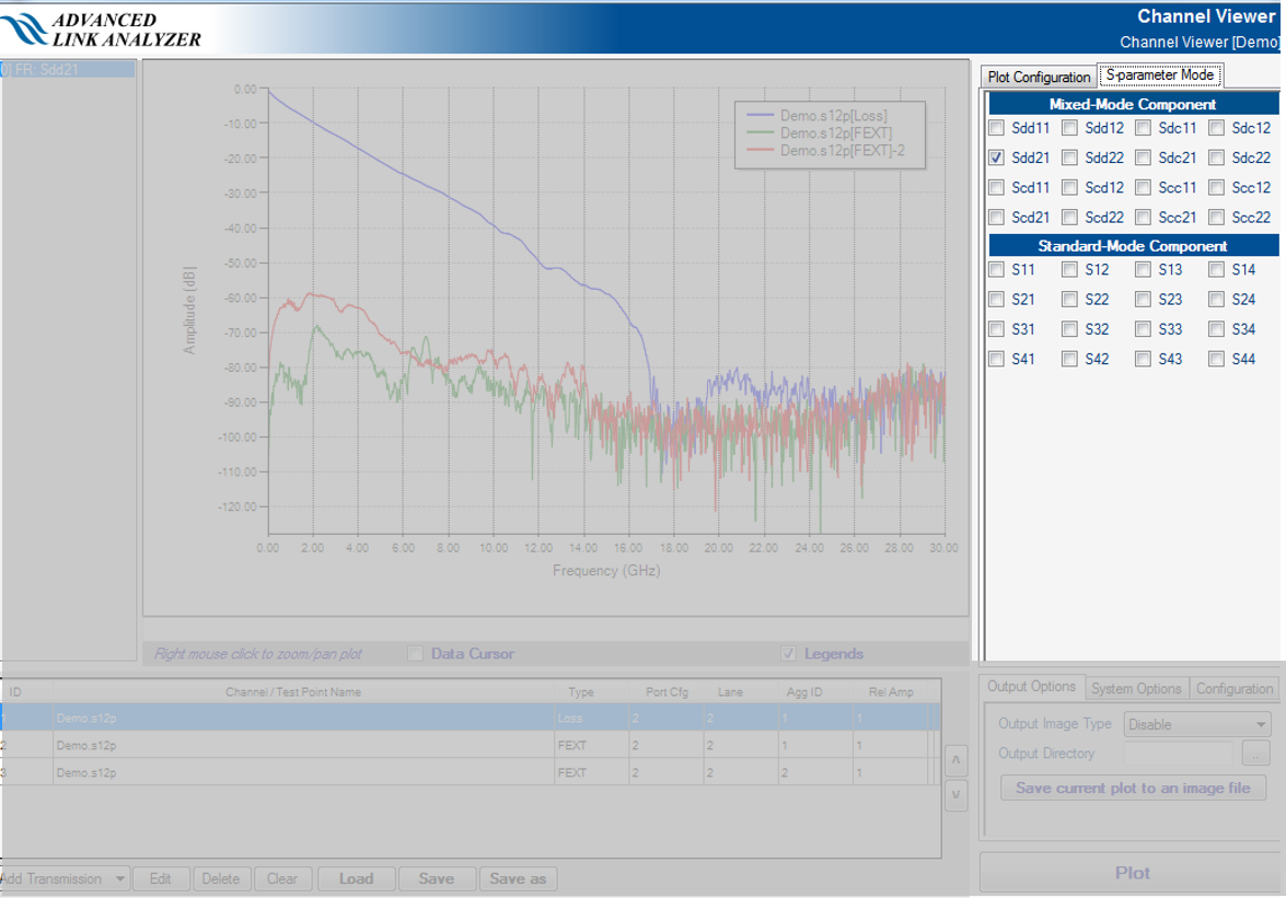
- Mixed-Mode Selector Panel—This panel allows you to select and plot an S-parameter’s mixed-mode characteristics. The Intel® Advanced Link Analyzer Channel Viewer can convert standard-mode (that is, single-ended) frequency responses into its differential–pair format (mixed-mode) frequency responses. For high-speed serial links with differential signaling scheme, Intel recommends you observe channel characteristics and performance in mixed-mode.
- Standard-Mode Selector Panel—This panel allows you to select and plot an S-parameter’s standard-mode characteristics. An open 4-port single-ended S-parameter is supported in this plot mode.