A newer version of this document is available. Customers should click here to go to the newest version.
4.4. Intel® FPGA PTC - Main Page
The required parameters depend on whether the junction temperature is manually entered or auto computed.
| Parameter | Description |
|---|---|
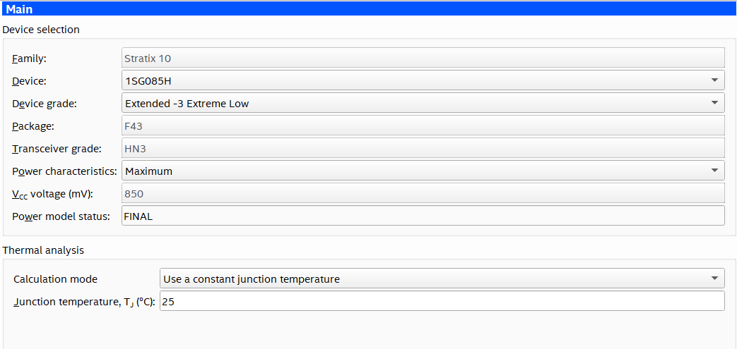
| Family | Shows the device family selected at startup, either directly or through the imported file. |
| Device | Select your device. Larger devices consume more static power and have higher clock dynamic power. All other power components are unaffected by device selection. |
| Device Grade | Select the combination of Operating Temperature, Speed Grade, and Power Option used. Refer to the device datasheet for available combinations. |
| Package | Select the device package. Larger packages provide a larger cooling surface and more contact points to the circuit board, thus they offer lower thermal resistance. Package selection does not affect dynamic power directly. |
| Transceiver Grade | Select the transceiver grade.
Note: For information on transceiver grades, refer to the Device Overview document for a given device family.
|
| Power characteristics | Select typical or maximum power. There is a process variation from die-to-die. This variation primarily affects static power consumption. If you choose Typical power characteristics, estimates are based on longterm projections of average power consumed by typical silicon. For FPGA board power supply design and thermal design, choose Maximum for worst-case values.
Note: Typical power characteristics should not be used for regulator sizing or thermal analysis; use maximum power characteristics for these activities.
|
| VCC Voltage (mV) | (This field appears in the Intel® Stratix® 10 PTC only.) |
| Power Model Status | Indicates whether the power model for the device is in advance, preliminary, or final status. |
The Thermal Analysis section displays the junction temperature (TJ) and other thermal parameters, depending on the thermal analysis mode.
| Column Heading | Description |
|---|---|
| Calculation mode | Specifies the calculation mode for the thermal solver to use. The available choices are:
Note: For more detailed information on Calculation mode settings, refer to Intel® FPGA PTC - Thermal Page.
|
| Junction temperature, TJ (°C) | Specify the junction temperature for all dies in the package. This field is available when you select Use a constant junction temperature as the Calculation mode. In this mode, the junction temperatures for all dies in the package are assumed to have the specified value. To automatically compute junction temperatures, select one of the other options in the same field. |