F-Tile Avalon® Streaming IP for PCI Express* User Guide
ID
683140
Date
10/16/2025
Public
1. Acronyms
2. Introduction
3. IP Architecture and Functional Description
4. Advanced Features
5. Interfaces
6. Parameters
7. Testbench
8. Troubleshooting/Debugging
9. F-Tile Avalon Streaming IP for PCI Express User Guide Archives
10. Revision History for the F-Tile Avalon Streaming IP for PCI Express User Guide
A. Configuration Space Registers
B. Implementation of Address Translation Services (ATS) in Endpoint Mode
C. Packets Forwarded to the User Application in TLP Bypass Mode
D. Root Port Enumeration
E. Bifurcated Endpoint Support for Independent Resets
3.1. Architecture
3.2. Functional Description
3.3. Avalon-ST TX/RX
3.4. Interrupts
3.5. Completion Timeout
3.6. Hot Plug
3.7. Power Management
3.8. Configuration Output Interface (COI)
3.9. Configuration Intercept Interface (EP Only)
3.10. Hard IP Reconfiguration Interface
3.11. PHY Reconfiguration Interface
3.12. Page Request Service (PRS) (EP Only)
5.1. Overview
5.2. Clocks and Resets
5.3. Serial Data Interface
5.4. Avalon-ST Interface
5.5. Interrupt Interface
5.6. Hard IP Status Interface
5.7. Error Interface
5.8. 10-bit Tag Support Interface
5.9. Completion Timeout Interface
5.10. Power Management Interface
5.11. Hot Plug Interface (RP Only)
5.12. Configuration Output Interface
5.13. Configuration Intercept Interface (EP Only)
5.14. Hard IP Reconfiguration Interface
5.15. PHY Reconfiguration Interface
5.16. Page Request Service (PRS) Interface (EP Only)
5.17. FLR Interface Signals
5.18. PTM Interface Signals
5.19. VF Error Flag Interface Signals
5.20. VirtIO PCI Configuration Access Interface Signals
6.2.3.1. Device Capabilities
6.2.3.2. Link Capabilities
6.2.3.3. Legacy Interrupt Pin Register
6.2.3.4. MSI Capabilities
6.2.3.5. MSI-X Capabilities
6.2.3.6. Slot Capabilities
6.2.3.7. Latency Tolerance Reporting (LTR)
6.2.3.8. Process Address Space ID (PASID)
6.2.3.9. Device Serial Number Capability
6.2.3.10. Page Request Service (PRS)
6.2.3.11. Access Control Service (ACS) Capabilities
6.2.3.12. Power Management
6.2.3.13. Vendor Specific Extended Capability (VSEC) Registers
6.2.3.14. Precision Time Measurement (PTM)
6.2.3.15. Address Translation Services (ATS)
6.2.3.16. TLP Processing Hints (TPH)
6.2.3.17. VirtIO Parameters
6.2.3.18. Receiver Detection
7.6.1. ebfm_barwr Procedure
7.6.2. ebfm_barwr_imm Procedure
7.6.3. ebfm_barrd_wait Procedure
7.6.4. ebfm_barrd_nowt Procedure
7.6.5. ebfm_cfgwr_imm_wait Procedure
7.6.6. ebfm_cfgwr_imm_nowt Procedure
7.6.7. ebfm_cfgrd_wait Procedure
7.6.8. ebfm_cfgrd_nowt Procedure
7.6.9. BFM Configuration Procedures
7.6.10. BFM Shared Memory Access Procedures
7.6.11. BFM Log and Message Procedures
7.6.12. Verilog HDL Formatting Functions
3.1.2.1. Guidelines for System PLL Reference Clock
One of the reference clock pins refclk[0] to refclk[7] can also be shared as the reference clock to the System PLL which generates the pld_clk and coreclkout_hip clocks. The reference clock must adhere to the following requirements:
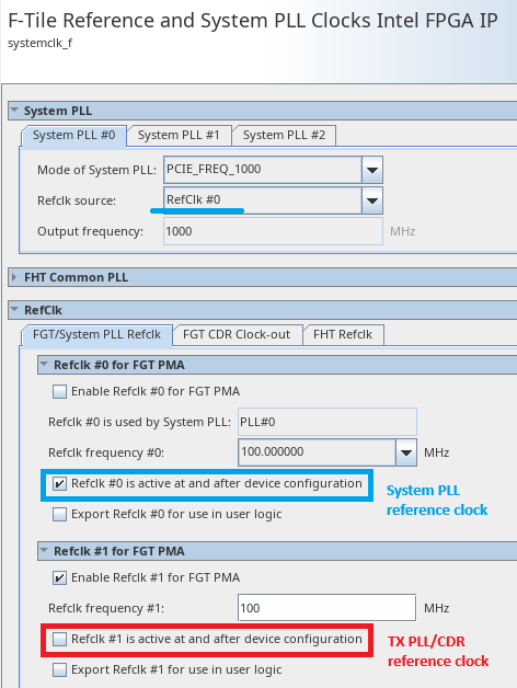
- If compliance to PCIe link training timing specifications is required, the reference clock to the System PLL must be available and stable before device configuration begins. You must set the Refclk is active at and after device configuration parameter in the System PLL IP to On. Derive the reference clock from an independent and free-running clock source. Alternatively, in a closed system, if the reference clock from the PCIe link is guaranteed available before device configuration starts, you can use it to drive the System PLL. Once the PCIe link refclk is alive, it can never be allowed to go down.
- If compliance to PCIe link training timing specifications is not required and the reference clock to the System PLL may not be available before device configuration starts, you must set the Refclk is active at and after device configuration parameter in the System PLL IP to Off. In this case, you may use the reference clock from the PCIe link to drive the System PLL.
Figure 8. System PLL Reference Clock in the IP Parameter Editor
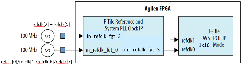
The figure below shows an example where an independent reference clock drives the System PLL (via the in_refclk_fgt_0 port). It does not share the reference clock from the PCIe link which is not available before device configuration starts.
Figure 9. Independent Refclk to System PLL
Once the reference clock for the System PLL is up, it must be stable and present throughout the device operation and must not go down. If you are not able to adhere to this requirement, you must reconfigure the device.
Note: For additional information of restrictions on reference clock and the System PLL, refer to the Clock Rules and Restrictions section in F-Tile Architecture and PMA and FEC Direct PHY IP User Guide.