F-Tile Avalon® Streaming IP for PCI Express* User Guide
ID
683140
Date
10/16/2025
Public
1. Acronyms
2. Introduction
3. IP Architecture and Functional Description
4. Advanced Features
5. Interfaces
6. Parameters
7. Testbench
8. Troubleshooting/Debugging
9. F-Tile Avalon Streaming IP for PCI Express User Guide Archives
10. Revision History for the F-Tile Avalon Streaming IP for PCI Express User Guide
A. Configuration Space Registers
B. Implementation of Address Translation Services (ATS) in Endpoint Mode
C. Packets Forwarded to the User Application in TLP Bypass Mode
D. Root Port Enumeration
E. Bifurcated Endpoint Support for Independent Resets
3.1. Architecture
3.2. Functional Description
3.3. Avalon-ST TX/RX
3.4. Interrupts
3.5. Completion Timeout
3.6. Hot Plug
3.7. Power Management
3.8. Configuration Output Interface (COI)
3.9. Configuration Intercept Interface (EP Only)
3.10. Hard IP Reconfiguration Interface
3.11. PHY Reconfiguration Interface
3.12. Page Request Service (PRS) (EP Only)
5.1. Overview
5.2. Clocks and Resets
5.3. Serial Data Interface
5.4. Avalon-ST Interface
5.5. Interrupt Interface
5.6. Hard IP Status Interface
5.7. Error Interface
5.8. 10-bit Tag Support Interface
5.9. Completion Timeout Interface
5.10. Power Management Interface
5.11. Hot Plug Interface (RP Only)
5.12. Configuration Output Interface
5.13. Configuration Intercept Interface (EP Only)
5.14. Hard IP Reconfiguration Interface
5.15. PHY Reconfiguration Interface
5.16. Page Request Service (PRS) Interface (EP Only)
5.17. FLR Interface Signals
5.18. PTM Interface Signals
5.19. VF Error Flag Interface Signals
5.20. VirtIO PCI Configuration Access Interface Signals
6.2.3.1. Device Capabilities
6.2.3.2. Link Capabilities
6.2.3.3. Legacy Interrupt Pin Register
6.2.3.4. MSI Capabilities
6.2.3.5. MSI-X Capabilities
6.2.3.6. Slot Capabilities
6.2.3.7. Latency Tolerance Reporting (LTR)
6.2.3.8. Process Address Space ID (PASID)
6.2.3.9. Device Serial Number Capability
6.2.3.10. Page Request Service (PRS)
6.2.3.11. Access Control Service (ACS) Capabilities
6.2.3.12. Power Management
6.2.3.13. Vendor Specific Extended Capability (VSEC) Registers
6.2.3.14. Precision Time Measurement (PTM)
6.2.3.15. Address Translation Services (ATS)
6.2.3.16. TLP Processing Hints (TPH)
6.2.3.17. VirtIO Parameters
6.2.3.18. Receiver Detection
7.6.1. ebfm_barwr Procedure
7.6.2. ebfm_barwr_imm Procedure
7.6.3. ebfm_barrd_wait Procedure
7.6.4. ebfm_barrd_nowt Procedure
7.6.5. ebfm_cfgwr_imm_wait Procedure
7.6.6. ebfm_cfgwr_imm_nowt Procedure
7.6.7. ebfm_cfgrd_wait Procedure
7.6.8. ebfm_cfgrd_nowt Procedure
7.6.9. BFM Configuration Procedures
7.6.10. BFM Shared Memory Access Procedures
7.6.11. BFM Log and Message Procedures
7.6.12. Verilog HDL Formatting Functions
6.2.6. Analog Options
Figure 74. Analog Parameters Tab
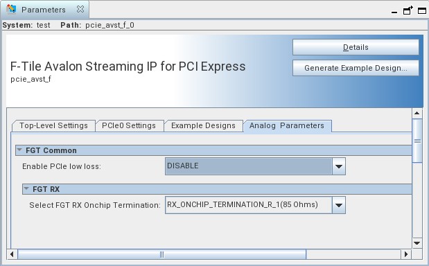
| Parameter | Value | Default Value | Description |
|---|---|---|---|
| Enable PCIe low loss | Disable/Enable | Enable | When you select Enable, you enable the transceiver analog settings for low loss PCIe design.
Note: This parameter should only be enabled for chip-to-chip design where the insertion loss from endpoint silicon pad to root port silicon pad including the package insertion loss is below 8 dB at 8GHz.
|
| Select FGT RX Onchip Termination | RX_ONCHIP_TERMINATION_R_1 (85 Ohms) RX_ONCHIP_TERMINATION_R_2 (100 Ohms) |
RX_ONCHIP_TERMINATION_R_1 (85 Ohms) | Select the on-chip termination impedance value to differentiate the data trace at the receive side. |