This technical article is intended to address an issue discovered in some Original Equipment Manufacturers (OEM) or Original Design Manufacturers (ODM) production systems where system firmware (FW) or an Integrated Firmware Image (IFWI) was found to contain one or more preproduction or example test keys. The private keys for these preproduction or test keys were often included in system Basic Input Output System (BIOS) development information provided to OEMs or ODMs for their use in platform development and testing and were not intended to be used in production systems or environments.
Given the rise of recent cyber-attacks in the industry that have involved exfiltration of BIOS source code and OEM private keys, this paper provides guidance on the importance of protecting OEM private keys. The Development and Test Keys section offers more details about the potential impact of public exposure of test private keys.
Document Scope
This document provides background information on manifesting and signing of Intel and OEM components and the establishment of the Chain of Trust (COT). This article includes some information on Intel® Boot Guard data structures as well as an example to demonstrate the COT flow through loading of the Initial Boot Block, which represents the hand-off to BIOS. The information in this document is generally limited to products based on 13th Generation Intel® Core™ Processor platforms and 3rd Generation Intel® Xeon® Scalable Processor platforms, or earlier. Guidance for manifesting and signing components for future products is subject to change.
Background
When OEMs or ODMs develop platforms, the system BIOS is also developed to handle setup and configuration of system hardware to prepare for and to initiate loading of an operating system (OS). Additionally, the OEM or ODM may develop firmware for other microcontrollers in the system (such as Integrated Sensor Hub (ISH) or may include Intel FW for other system agents (such as Intel® Converged Security and Management Engine (Intel® CSME)). These firmware components are integrated together into an Integrated Firmware Image (IFWI) which is programmed into the system flash or eMMC for use. OEMS and ODMs can activate several features that use key-based technology to protect the integrity of the firmware and IFWI, block unauthorized replacement of the IFWI, and ensure system integrity when booting the OS. Additionally, OEMs and ODMs should review their methods for protecting their private keys to ensure that these keys remain secure.
Intel provides OEMs, ODMs, and Independent BIOS Vendors (IBVs) source code and binary code modules that serve as a reference for how to develop system BIOS and other platform FW, as well as tools to manage the setup and configuration of that firmware. Intel provides training and reference documentation to educate customers on recommended methods for how to develop a properly configured and secure system.
In the reference code provided for the above purposes, Intel included documentation and examples for how to build the reference version of the firmware, including example keys to demonstrate the process. The documentation enumerated the process necessary to build a production level IFWI, called out required configuration changes, and explained both how to generate private/public key pairs and how to replace the example keys with OEM / ODM / IBV production keys. However, some production systems have been identified that were using the example keys from the reference code instead of OEM/ODM generated keys.
| Term | Description |
|---|---|
| ACE | Audio and Context Engine |
| ACM | Authenticated Code Module |
| CSME | Converged Security Management Engine |
| EOM | End of Manufacturing |
| FPF | Field Programmable Fuses |
| FW | Firmware |
| FVC | Firmware Version Control |
| HW | Hardware |
| IBB | Initial Boot Block |
| IFWI | Integrated Firmware Image (system firmware image on serial platform interface) |
| Intel® DAL | Intel® Dynamic Application Loader |
| Intel® MEU | Intel® Manifest Extension Utility |
| Intel® MFIT | Intel® Modular Flash Image Tool |
| ISH | Integrated Sensor Hub |
| IUP | Independently Updatable Partition |
| OEM KM | Original Equipment Manufacturer Key Manifest (containing OEM public key hashes to authenticate OEM-signed firmware components. |
| OS | Operating System |
| PCH | Platform Controller Hub |
| PKH | Public Key Hash |
| ROT KM | Root of Trust Key Manifest (containing Intel public key hases to authenticate Intel-signed firmware components) |
| SPI | Serial Peripheral Interface |
| SVN | Security Version Number. Used in firmware upgrade/downgrade capabilities. |
| VCN | Version Control Number. Used in firmware upgrade/downgrade capabilities. |
Introduction to Signing
Why is Signing Important?
It is critical for platform safety to make sure that the firmware is loaded upon boot from a trusted source. The process of signing the firmware components ensures that the owner of the component (whether that is an OEM or Intel) authorizes the loading and running of their component on the platform.
This is possible by establishing a chain of trust starting from the hardware of the platform itself. The hardware authenticates a key manifest (KM), and the key manifest is then used to authenticate other firmware components, as shown in Figure 1 below.
Who Performs the Signing?
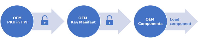
Intel signs all firmware components to be loaded by the Intel® CSME. OEMs may add or replace capabilities for several components, such as ISH and Audio and Context Engine (ACE). Components must be signed, and an OEM KM is required to load any OEM components and use their capabilities.
If an OEM wishes to only use the Intel-provided components, the OEM is not required to sign anything, and no OEM KM is added to the IFWI.
When is Signing Performed?
Research and development facilities sign components and create and sign the OEM KM prior to manufacturing. At the time of manufacturing, the ready-signed OEM components and OEM KM are entered into the image creation tool (Intel® MFIT), and when the IFWI is flashed, the key used to authenticate the OEM KM is burned to the fuses. This will be discussed in greater detail in the following chapters.
Theory of Signing
This section discusses the theory of signed structures, signing components, and how authentication is performed during boot flow.
Cryptography Basics
Both the signing flow and the process to establish a chain of trust are based on the concepts of cryptography. The signing process uses two cryptographic functions: hashing and RSA data encryption.
Hashing
Hashing is a one-directional mathematical operation which is simple to calculate, yet computationally difficult to reverse. Hashing produces completely different outputs even with small changes in the input data.
For products currently in the market, the hashing functions used are SHA-256 and SHA-384 which are from the SHA2 family of cryptographic functions, or ShangMI 3 (SM3), which is a hash function similar to SHA2.
Data Encryption using RSA Algorithm
Using a private and public key pair which are mathematically linked, data can be encrypted and then decrypted (a process known as reverse encryption). The private key is used to encrypt the data, and then the public key can be used to decrypt it back to the original source data.
In the signing process of components, the data being encrypted is the hash of the original binary component, and the public key is used to decrypt the data back to its original format during verification. It is important for the private key to be stored securely, so that only the originating entity can perform the encryption. The public key is available to the public, since once the key is used to decrypt the signature, the output is compared with the binary hash present in the component. The data will only match if the public key mathematically corresponds perfectly to the private key used during encryption.
IFWI Boot Trust Flow
The Chain of Trust (COT) begins with the hash of the OEM public key, which is programmed into field programmable fuses (FPF) at the end of the manufacturing process. Multiple technologies are chained together to verify that authorized firmware and software is being used throughout the system BIOS and OS boot process.
Boot Flow Overview
Figure 2 is a high-level representation of the boot flow that depicts the signing authority for each of the boot modules. At system power up, the management engine (ME) begins executing, and then authenticates and loads runtime updates and OS FW for the ME and Power Management Controller (PMC). The PMC/ME performs a host reset to the CPU. Prior to fetching any BIOS code, the CPU begins by verifying the firmware interface table (FIT) and then authenticates and loads the microcode update (MCU). If the FIT has an entry for an Authenticated Code Module (ACM), the CPU loads the ACM, authenticates it, and then executes it. The ACM loads and verifies the Boot Policy Manifest (BPM) and executes the Initial Boot Block (IBB). The IBB verifies the hash of the OEM Boot Block (OBB) and then executes the OBB followed by the OS boot loader. The OS boot loader then loads the SINIT ACM, which is authenticated by hardware. The setup necessary to maintain the chain of trust for loading the OS or Virtual Memory Manager (VMM) is complete when the SINIT ACM is executed.
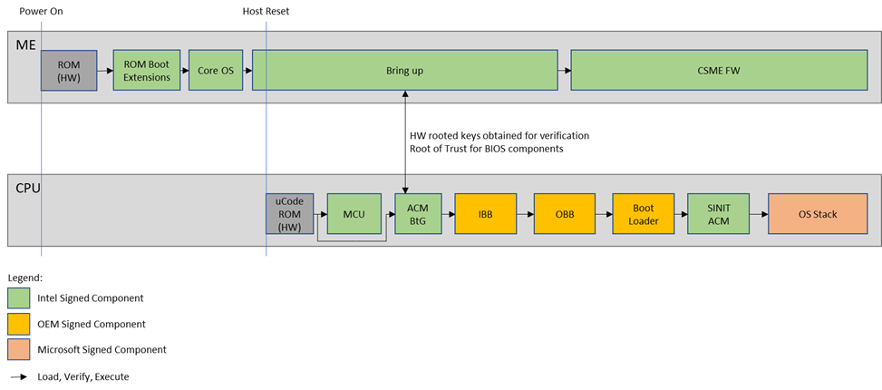
Note that, as shown in the figure above, the platform OEM is responsible for the chain of trust through the IBB, OBB, and loading of the Boot Loader portions of the system BIOS, and Microsoft is responsible for signing the initial OS module to load the OS/VMM (Secure Boot).
Field Programmable Fuses
The field programmable fuses (FPFs) are used by platform manufacturers to provision the boot policy to be used on the system. They provide the foundational mechanism for verifying the integrity of the KM and BPM.
The FPFs are persistently stored in the Platform Controller Hub (PCH), and once provisioned, a hardware lock is closed. The fuses cannot be changed for the life of the platform. This is referred to as the End of Manufacturing (EOM). The FPFs are not directly accessible by the OEM and can only be programmed via the manageability engine in the PCH. Thus, Intel provides special tools to allow the OEM to specify their boot policy and public key hash value.
FPF policies are clustered in registers: Restrictions (BP.RSTR), Type (BP.Type), and Revocation (BP.Revocation). None of these FPF registers are directly accessible by BIOS. Policies set by these FPF registers are read by S-ACM and propagated to BIOS via the BTG_SACM_INFO model specific register (MSR) and ACM_POLICY_STATUS register.
Another notable FPF register is BP.KEY, which holds the digest of KM signing key. This register is used by S-ACM and SINIT ACM and is available to BIOS or information tools via the Read File command.
Analyzing the Integrated Firmware Image (IFWI)
The following discussion is a look at the IFWI and the primary structures within it that are used to hold keys and information that are used in the authentication and signature verification phases when loading FW components during the boot flow to ensure only FW that has been authorized by the OEM is loaded. The basic flow of steps is shown to describe how the flow should work when properly configured with some discussion of errors or decisions made with regards to implementation and how that may affect system security.
Typical systems, both client and server, store the IFWI in flash memory that is in the physical memory address range immediately below the 4 GB boundary (ending at address 0FFFFFFFFh). The lowest extent of the flash device depends on the size of device that was selected to hold the required FW. The size of the device is commonly in the range of 8 MB to 64 MB. So, as an example, if a system uses a 32 MB flash device, the device will be addressed starting from the address 4 GB - 32 MB or in the address range of 0FE000000h – 0FFFFFFFFh.
To analyze the IFWI, many techniques may be used to collect the IFWI image. Some examples include saving the IFWI from the EFI prompt, using various utilities to read the IFWI, saving the image using a tool provided by the OEM or BIOS vendor, or downloading a BIOS image from the OEM website and extracting the IFWI. Note that BIOS updates from OEMs can come in several forms, ranging from a full IFWI to capsule update files (which are just updates for selected portions of the IFWI), to custom firmware images that contain additional security layers intended to block malicious IFWI updates. This document is not intended to explain the details of extracting the IFWI image, but rather how to look at the key signing elements of the IFWI after an image is available.
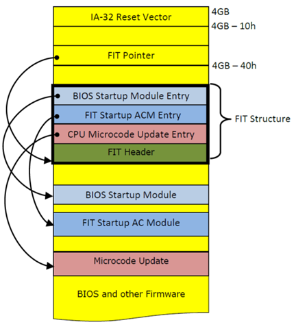
Firmware Interface Table (FIT)
A FIT is a data structure inside BIOS flash and consists of multiple entries. Each entry defines the starting address and attributes of different components in the BIOS. FIT resides in the BIOS flash area and is located by a FIT pointer at physical address (4GB - 40h). Refer to Figure 3 below.
The FIT is generated at build time based on the size and location of the firmware components.
The CPU processes the FIT before executing the first BIOS instruction located at the reset vector (address 0FFFFFFF0h). If a microcode update for the board support package (BSP) is pointed by a FIT type 1 entry, the MCU is loaded before executing the BIOS code at the reset vector and is applied to all threads within the package. An OEM BIOS may provide a facility for system software to manage the processor MCU. It is BIOS’s responsibility to ensure the validity and the integrity of the update before incorporating it into the IFWI in flash memory.
Refer to the FIT specification for complete documentation.
The FIT pointer points to the first byte of the Header (type 0) entry in the FIT. Each entry in the Firmware Interface Table is 16 bytes in length. The entry type can be found 14 bytes from the beginning of the FIT entry and is indicated using bits 6:0. The fixed address of the object pointed to is at an offset of 0 bytes (8 bytes in length).
| Byte Offsets | 15 | 14 | 13:12 | 11 | 10:8 | 7:0 |
|---|---|---|---|---|---|---|
| Meaning | Checksum | Bit 7 - C_V Bits 6:0 - Type |
Version | Reserved | Size | Address |
| FIT Entry Type | Description (Intel® 64 and IA-32 Architectures) |
|---|---|
|
0x00 |
FIT Header Entry |
|
0x01 |
Microcode Update Entry |
|
0x02 |
Startup AC Module Entry |
|
0x03 |
Diagnostic AC Module Entry |
|
0x04 – 0x06 |
Intel Reserved |
|
0x07 |
BIOS Startup Module Entry |
|
0x08 |
TPM Policy Record |
|
0x09 |
BIOS Policy Record |
|
0x0A |
TXT Policy Record |
|
0x0B |
Key Manifest Record |
|
0x0C |
Boot Policy Manifest |
|
0x0D - 0x0F |
Intel Reserved |
|
0x10 |
CSE Secure Boot |
|
0x11 - 0x2C |
Intel Reserved |
|
0x2D |
Feature Policy Delivery Record |
|
0x2E |
Intel Reserved |
|
0x2F |
JMP $ Debug Policy |
|
0x30 - 0x70 |
Reserved for Platform Manufacturer Use |
|
0x71 - 0x7E |
Intel Reserved |
|
0x7F |
Unused Entry (skip) |
FIT Example
For this paper, two items of interest in the FIT are the Key Manifest entry and the Boot Policy Manifest entry. These entries are used to authenticate the integrity of FW volumes before executing the code or using data contained within those volumes.
Note: When locating the various structures discussed below, look for the UEFI Structure ID. Many of these structures contain a UEFI Structure ID string to mark the beginning of the structure. The combination of the address in the FIT as well as the UEFI Structure ID can be used to verify the location of the structure. An example of this can be seen below. The FIT Pointer is shown below (little endian format) and highlighted in italic.
ffffffc0: 0083 ffff 0000 0000 0000 0000 0000 0000 ................
ffffffd0: bf50 41eb 1d00 0000 0000 0000 0000 0000 .PA.............
ffffffe0: 183b feff ebfe cf00 0000 0000 0000 0000 .;..............
fffffff0: 9090 e9bb fd00 0000 e000 0000 0000 feff ................
The FIT pointer above (at 0FFFFFFC0h) contains the fixed address of 0FFFF8300h, where the FIT is found and confirmed with the _FIT_ structure ID value in the first record. In the data below, the FIT entry types are highlighted in bold, and the addresses of those structures are highlighted in bold italic.
ffff8300: 5f46 4954 5f20 2020 0e00 0000 0001 0056 _FIT_ .......V
ffff8310: 6000 d2ff 0000 0000 0000 0000 0001 0100 `...............
ffff8320: 6050 d3ff 0000 0000 0000 0000 0001 0100 `P..............
ffff8330: 60cc d4ff 0000 0000 0000 0000 0001 0100 `...............
ffff8340: 60f8 d5ff 0000 0000 0000 0000 0001 0100 `...............
ffff8350: 6024 d7ff 0000 0000 0000 0000 0001 0100 `$..............
ffff8360: 0080 ecff 0000 0000 0000 0000 0001 0200 ................
ffff8370: 0084 ffff 0000 0000 c007 0000 0001 0700 ................
ffff8380: 0000 edff 0000 0000 0010 0100 0001 0700 ................
ffff8390: 0000 ceff 0000 0000 0030 0000 0001 0700 .........0......
ffff83a0: 0000 deff 0000 0000 00e8 0000 0001 0700 ................
ffff83b0: 0000 feff 0000 0000 9017 0000 0001 0700 ................
ffff83c0: 0079 ffff 0000 0000 4102 0000 0001 0b00 .y......A.......
ffff83d0: 007e ffff 0000 0000 eb02 0000 0001 0c00 .~..............
OEM Key Manifest (OEM KM)
The OEM Key Manifest plays a central part in the signing mechanism. The OEM KM lists the public key hashes used to authenticate the OEM-created binaries to be loaded. The OEM Key Manifest itself is signed, and its corresponding public key hash is programmed into the FPF at the End of Manufacturing (EOM). This creates a secure verification mechanism where firmware verifies that the OEM Key Manifest was signed with a key owned by the OEM. Once the OEM KM is authenticated, each public key hash stored within the OEM KM can authenticate the corresponding FW component.
Important Note! Since the hash fused into the platform hardware can never be changed, it is critical to secure the private key used to sign the OEM Key Manifest. If at any stage an OEM would like to update the image on the platform, the OEM KM for the new image must be signed with the same key used for the original OEM KM.
OEM KM Manifest Data Description
The OEM KM (and BPM) uses a key based on an RSA private/public key pair. The requirements for the key and hash functions used can be determined by parsing the KM. For current products, two structure formats have been used for the KM header and the specific format can be determined from the Structure Version value, 0x10 and 0x21. Note, this data should be considered an example for understanding as the format of these structures will continue to change. These structures are shown in Table 4 and Table 5.
| Field | Size (Bytes) | Description |
|---|---|---|
|
StructureID |
8 |
‘__KEYM__’. Abbreviation of Key Manifest |
|
Structure Version |
1 |
10h |
|
Key Manifest Version |
1 |
Version of the Key Manifest defined by the Platform Manufacturer. The actual value is transparent to Boot Guard and is not processed by Boot Guard. |
|
KMSVN |
1 |
Bit definition: |
|
KeyManifestID |
1 |
7:4 – Reserved. Must be 0 |
|
BPKey |
Size of (SHA_HASH _STRUCTURE) |
KeyHash for Public Key used to sign BPM |
|
KeyManifestSignature |
Size of (KEY_AND_SIGNATURE _STRUCT) |
Key manifest signature with Public Key stored in FPF |
| Field | Size (Bytes) | Description |
|---|---|---|
|
StructureID |
8 |
‘__KEYM__’. Abbreviation of Key Manifest |
|
Structure Version |
1 |
21h |
|
Reserved |
3 |
Alignment, must be 0 |
|
KeySignatureOffset |
2 |
Key Manifest Signature offset |
|
Reserved 2 |
3 |
Alignment, must be 0 |
|
KeyManifestRevision |
1 |
Revision of the Key Manifest defined by the Platform Manufacturer |
|
KMSVN |
1 |
Bits 7:4 – Reserved, must be zero |
|
Key Manifest ID |
1 |
The key Manifest Identifier (KMID) |
|
KmPubKeyHashAlg |
2 |
Hash algorithm of OEM public key digest programmed into the FPF |
|
KeyCount |
2 |
Count of KeyHash structures |
|
KmHash[KeyCount] |
KeyCount * Size of (SHA_KMHASH _STRUCTURE) |
Array of KmHash structures. |
|
KeyM12anifestSignature |
Size of (KEY_AND_SIGNATURE _STRUCT) |
Key manifest signature with Public Key stored in FPF |
The following format primitives are used by many fields of the following data structures. These primitives can be found in the document TCG Trusted Platform Module Library, Family 2.0.
For reference, the format primitives are listed here:
TPM_ALG_SHA1 = 0x0004 – hash algorithm
TPM_ALG_SHA256 = 0x000B – hash algorithm
TPM_ALG_SHA384 = 0x000C – hash algorithm
TPM_ALG_SM3_256 = 0x0012 – hash algorithm
TPM_ALG_RSA = 0x0001 – key algorithm
TPM_ALG_ECC = 0x0023 – key algorithm
TPM_ALG_RSASSA = 0x0014 – signature scheme
TPM_ALG_RSAPSS = 0x0016 – signature scheme
TPM_ALG_ECDSA = 0x0018 – signature scheme
TPM_ALG_SM2 = 0x001B – signature scheme
TPM_ALG_NULL = 0x0010 – NULL algorithm
| Field | Size (Bytes) | Description |
|---|---|---|
| Usage | 8 | Digest usage bitmask See Table 7 for assigned bit positions More than one bit can be set to indicate shared digest usage. |
| Digest |
Size of (SHA_HASH _STRUCTURE) |
KeyHash - Actual digest description structure |
| Bit | Usage |
|---|---|
|
0 |
Boot Policy Manifest signing pubkey digest |
|
1 |
FIT Patch Manifest signing pubkey digest |
|
2 |
ACM Manifest signing pubkey digest |
|
3 |
SDEV signing pubkey digest. |
|
4 |
PFR CPLD Root of Trust pubkey digest |
|
5 - 32 |
Reserved for Intel Use |
|
33 |
iUnit BootLoader Manifest |
|
34 |
iUnit Main FW Manifest |
|
35 |
Audio Image0 Manifest |
|
41 |
ISH Manifest |
|
43 |
OEM Debug Manifest (token) |
|
45 |
OEM Key Manifest |
|
53 |
OEM Dnx Ifwi Manifest |
|
57 |
OEM Descriptor Manifest |
| Field | Size (Bytes) | Description |
|---|---|---|
|
HashAlg |
2 |
Hash Algorithm ID – one of TPM_ALG_ID values |
|
Size |
2 |
Digest size in bytes – one of ALG_DIGEST_SIZE values matching HashAlg |
|
HashBuffer |
Size of Hash |
The buffer containing digest value. |
| Field | Size (Bytes) | Description |
|---|---|---|
|
Version |
1 |
Must be 10h |
|
KeyAlg |
2 |
TPM_ALG_RSA |
|
Key |
Size of (RSA_PUBLIC_KEY _STRUCT) |
RSA public key structure |
|
SigScheme |
2 |
TPM_ALG_RSASSA or TPM_ALG_RSAPSS Note: TPM_ALG_RSASSA is intended to indicate use of the RSASSA-PKCS1-v1_5 signature format and TPM_ALG_RSAPSS is the RSASSA-PSS signature format. |
|
Signature |
Size of (RSA_SIGNATURE _STRUCT) |
RSA signature structure |
| Field | Size (Bytes) | Description |
|---|---|---|
|
Version |
1 |
Must be 10h |
|
KeySize |
2 |
Number of bits in the modulus (2048 or 3072) |
|
Exponent |
4 |
The public exponent. Must be 10001h |
|
Modulus |
KeySize / 8 |
The modulus in Little Endian format |
| Field | Size (Bytes) | Description |
|---|---|---|
|
Version |
1 |
Must be 10h |
|
KeySize |
2 |
Number of bits in the modulus (2048 or 3072) |
|
HashAlg |
2 |
Hash algorithm used for signature (TPM_ALG_SHA256, TPM_ALG_SHA384) |
|
Signature |
KeySize / 8 |
RSASSA-PKCS1-v1_5 / RSASSA-PSS Signature |
| Field | Size (Bytes) | Description |
|---|---|---|
|
Version |
1 |
Must be 10h |
|
KeyAlg |
2 |
TPM_ALG_ECC |
|
Key |
Size of (ECC_PUBLIC_KEY _STRUCT) |
ECC public key structure |
|
SigScheme |
2 |
TPM_ALG_ECDSA or TPM_ALG_SM2 |
|
Signature |
Size of (ECC_SIGNATURE _STRUCT) |
ECC signature structure |
| Field | Size (Bytes) | Description |
|---|---|---|
|
Version |
1 |
Must be 10h |
|
KeySize |
2 |
Number of bits in the public key component (256 or 384 bits) |
|
Qx |
KeySize / 8 |
Qx coordinate |
|
Qy |
KeySize / 8 |
Qy coordinate |
| Field | Size (Bytes) | Description |
|---|---|---|
|
Version |
1 |
Must be 10h |
|
KeySize |
2 |
Number of bits in the public key component (256 or 384 bits) |
|
HashAlg |
2 |
Hash algorithm used by signing process (TPM_ALG_SHA256, TPM_ALG_SHA384, or TPM_ALG_SM3_256) |
|
R |
KeySize / 8 |
R component of signature in LE format (32 or 48 bytes) |
|
S |
KeySize / 8 |
S component of signature in LE format (32 or 48 bytes) |
OEM Key Manifest Example
Using the example IFWI above, the OEM Key Manifest can be located using FIT type 0bh record address of 0FFFF7900h. The KM structure can be identified with the UEFI Structure ID string of __KEYM__. The format of the KM structure may change over time. To identify the specific structure format, use the Structure ID and the Structure Version information to properly match the structure format.
In the following example, the Structure ID is __KEYM__, and the Structure Version is 10h. In comparing with OEM KM structures above, the Structure Version matches Table 4. If the Structure Version had been 21h, then the structure in Table 5 would be used.
ffff7900: 5f5f 4b45 594d 5f5f 1010 0001 0b00 2000 __KEYM__...... .
ffff7910: d550 2ff0 6169 9f9e 2b7c 64ab 4137 4f56 .P/.ai..+|d.A7OV
ffff7920: ae6f 45db 870d dba4 733d dc30 3238 78bb .oE…..s=.028x.
ffff7930: 1001 0010 0008 0100 0100 ff84 9b32 ff8a .............2..
ffff7940: 956b 5949 868d 6191 0165 1a35 ae51 182a .kYI..a..e.5.Q.*
ffff7950: 8f55 0592 a82f f14e 9640 3f35 c2fa d403 .U.../.N.@?5....
ffff7960: c8f9 1310 f0e4 adcf 747c 62a0 805d 40d8 ........t|b..]@.
ffff7970: 802e 4740 24df fd02 2889 9108 6ad8 18af ..G@$...(...j...
ffff7980: b83a 967d bee0 73a9 4b20 fa09 5751 e6be .:.}..s.K ..WQ..
ffff7990: 3d43 78c9 9429 f5af 93b1 b303 a588 6bc7 =Cx..)........k.
ffff79a0: d728 f451 eff0 f23a 0af9 812e b6c5 5b9b .(.Q...:......[.
ffff79b0: 1275 faeb d16a cedb 9f52 b08a 5ce7 802e .u...j...R..\...
ffff79c0: 0971 126f a691 0ace 7a70 b132 84e9 a12e .q.o....zp.2....
ffff79d0: 3f4f 953d e93e c0b1 941a 2b7e 6f47 c714 ?O.=.>....+~oG..
ffff79e0: e2d5 cb48 1a42 30c8 b803 2815 183a a32e ...H.B0...(..:..
ffff79f0: 5b19 9714 5063 176d da64 2485 c271 649d [...Pc.m.d$..qd.
ffff7a00: 6fe2 9007 60b5 27c8 6f51 6de7 3f5c 777a o..’`.'.oQm.?\wz
ffff7a10: 29aa 5417 3a2f 3b51 d071 3c4f 4c8c eeb8 ).T.:/;Q.q<OL...
ffff7a20: b0bc 3869 d5ab a074 3796 d8f6 5001 371e ..8i...t7...P.7.
ffff7a30: ea7b b1a1 472d 67ce 5dbf 1400 1000 080b .{..G-g.].......
ffff7a40: 00bd 948b 6f5b 5f59 6c78 557c e968 3985 ....o[_YlxU|.h9.
ffff7a50: 1452 e76e 87eb 475e 168e 31bf 52b8 6b7a .R.n..G^..1.R.kz
ffff7a60: 9e76 13d4 591a a72b 7f30 a831 205c 5487 .v..Y..+.0.1 \T.
ffff7a70: e4e0 42ae db36 8aee 4be8 dc3c 975e 4126 ..B..6..K..<.^A&
ffff7a80: 1f10 dc36 556c 041d c1ab fc25 6414 1c85 ...6Ul.....%d...
ffff7a90: 27c1 8854 3c64 f442 707c 622a 758a 817‘ '..T<d.Bp|b*u..|
ffff7aa0: 90d0 be27 d1c4 6d4d 6f28 a342 4aa9 f711 ’..'..mMo(.BJ...
ffff7ab0: 4e76 fe3e f32e 4936 4921 4339 6688 1f79 Nv.>..I6I!C9f..y
ffff7ac0: 53fb 650e b870 b4b8 113e e1c5 f43e 755a S.e..p...>...>uZ
ffff7ad0: 9cd9 68aa a16f a08d 6ced 5931 4888 a547 ..h..o..l.Y1H..G
ffff7ae0: adc8 716d 0591 11fa 092b d66e 976d c6f8 ..qm.....+.n.m..
ffff7af0: d48b 47e9 27d8 c8bd 08f1 02a2 b08b 2ed4 .’G.'...........
ffff7b00: d2c1 54d0 69dc 1eef 5aa7 881c 0342 928f ..T.i...Z....B..
ffff7b10: 2f55 c47e cfba 0349 c8e5 b006 1297 6037 /U.~...I......`7
ffff7b20: 4bcd 03f4 7e92 bac5 815d 9990 a118 0983 K...~....]......
ffff7b30: ace8 6bf8 9ff2 5216 916b 6da8 a30e 5c60 ..k...R..km...\`
ffff7b40: 11ff ffff ffff ffff ffff ffff ffff ffff ................
In reviewing this structure format, the OEM KM contains one public key hash (called BPKey), used to authenticate the public key used to sign the Boot Policy Manifest (BPM), and a public key and signature (called KeyManifestSignature) used to verify the authenticity of the OEM KM. Most of the structures defined in this paper may include other embedded structures. For example, within this OEM KM, there are two other structures: the SHA_HASH_STRUCTURE and the KEY_AND_SIGNATURE_STRUCT, as indicated in the Size column. Descriptions for these structures can be found in Table 7, Table 8, and Table 11. Just as in the case above, the specific structure definition may be dependent on data values.
When analyzing the example IFWI, we find that the BPKey value starts at an offset of 12 bytes from the start of the structure. The first element of BPKey is HashAlg (shown in gray below), which indicates the function used to generate the public key hash. The two-byte value of 000bh indicates the hash was generated using the SHA256 function. The next two bytes indicate the length of the hash value, (in this case, 0020h bytes). Finally, the next 32-bytes (0020h) is the hash value.
The KeyManifestSignature definition begins with a one-byte version value (10h), followed by KeyAlg that describes the format of the public key value. In the data above, the value of 0001h indicates the key is an RSA type. Because the key is an RSA key, the definition in Table 9 must be used. The next byte is a structure version (10h), followed by a two-byte KeySize value that indicates the key size (in bits). In the case above, the key is a 2048-bit key. The next two values are the RSA public key exponent (highlighted in cyan) and modulus (highlighted in green) values. The SigScheme and Signature elements complete the KeyManifestSignature structure. SigScheme describes the signature function used (in this case, 0014h, indicating RSASSA). The Signature element structure is shown in Table 11, which begins with a one-byte version value, followed by the KeySize and HashAlg values. In this case, the signature KeySize is 2048 bits, and it uses the SHA256 hashing algorithm. The final 2048 bits (256 bytes) is the resulting signature calculated using the private key.
Following the decoding of the OEM KM and proper verification of the OEM KM signature, the public key in the KeyManifestSignature is hashed and compared with the hash value programmed in the FPF. If the hash matches the FPF data, then the system will trust the public key hash stored in BPKey for the Boot Policy’s signature check.
Note: It is often prudent for the Platform Manufacturer to restrict the use of a “master” key (which is what they put into Boot Policy Key) and allow a “child” key to sign the BP Manifest. This way, if the “child” key is compromised, the platform manufacturer can either revoke the Key Manifest or simply use a new KeyManifestID without any impact to hardware (whether existing/shipped or new).
Hash Algorithm
The hash algorithm used may vary between products or between products intended for different markets. The specific hash function used is indicated in the IFWI data structures where the hash value appears.
Note: The data used in the hash of an RSA public key may vary between products; either performing the hash of the modulus or performing the hash of the modulus concatenated with the exponent.
To determine which method was used for a particular product, perform a calculation using both methods and compare the results. Note that for all calculations, the values are in little-endian (LE) format.
6th and 7th Generation Intel® Core™ Processor-based Platforms
- RSA key modulus size == 2048 bits (256 bytes) and standard exponent == 0x00010001 (4 bytes)
- Modulus (256 bytes) are hashed using SHA256 algorithm to obtain BP.KEY value.
- BP.KEY = SHA256 (KM.LE (Key.modulus))
Intel® Pentium® Silver N4200, N5030, N5040, Celeron® J3355, J3455, J4025, J4125, N3350, N4020, N4120, 8th, 9th, and 10th Generation Intel® Core™ Processor-based Platforms
- Key must use modulus size == 2048 bits (256 bytes) and standard exponent == 0x00010001 (4 bytes)
- Modulus and exponent must be concatenated to obtain 260 bytes, which are then hashed using SHA256 algorithm to obtain BP.KEY value.
- BP.KEY = SHA256 (KM.LE (Key.modulus) || LE (Key.exponent))
Intel® Atom x6000E Series, Intel® Pentium® Silver J5005, N5000 and Celeron® J4005, J4010, N4000, N4100 Processors, and 11th Generation Intel® Core™ Processor-based and later Platforms
- Key must use modulus size == 3072 bits (384 bytes) and standard exponent == 0x00010001 (4 bytes)
- Modulus and exponent must be concatenated to obtain 260 bytes, which are then hashed using SHA384 algorithm to obtain BP.KEY value.
- BP.KEY = SHA384 (KM.LE (Key.modulus) || LE (Key.exponent))
Server Platforms
- The value of BP.KEY register in server platforms use SHA256 or SM3 and does not have to include the exponent in the digest computation.
BP.KEY = SHA384 (KM.LE (Key.modulus))
BP.KEY = SM3 (KM.LE (Key.Qx) | KM.LE (Key.Qy))
Opting Out of the OEM KM
Intel recommends OEMs always add an OEM KM to their images, even if they have not yet identified a use for it at the time the IFWI is manufactured. This can be done by adding an empty OEM KM (no entries), which serves as a placeholder in the image. Later, the image can be updated to include an OEM KM with relevant keys and public key hashes.
However, OEMs may choose to not use an OEM KM in their images. If the OEM KM has not been configured at EOM, an FPF will be permanently set to indicate that the OEM KM is not present. Once this happens, that platform image cannot be updated to use an OEM KM. Note that Intel-provided components, such as Intel CSME FW, are authenticated using a key stored in hardware, and this authentication is performed regardless if the OEM KM is present or not.
Signed Components and Their Structure
The platform OEM may choose to replace certain FW components, such as the Intel ISH or ACE components, to replace or extend capabilities provided by Intel. Those FW components should be re-signed with the OEM key. In addition, there may be OEM-signed binaries that use the signing chain-of-trust to enable capabilities such as debug tokens that are used to enable features for debugging platform hardware and FW.
Each item that is signed begins with the same structure, a binary, and in the signing flow a manifest is added to the binary. The manifest is then signed, and the signature and public key are entered into the header of the manifest to create the final signed component binary.
Regardless of the type of binary being signed, all signed components have the same final structure of original binary and manifest, where the public key and signature are part of the manifest header. See Figure 4.

Key Security
Intel recommends using separate key pairs for signing each component. Using a single key for signing multiple components is not an advised security practice, since if the key is compromised, the entire package may be compromised.
Private production keys should always be stored securely and kept secret to provide a robust secure boot flow and firmware load. If the private keys are exposed, they may be used to create and sign unofficial versions of the binaries which can then be loaded onto the platform to compromise platform security.
It is important to restrict/audit access to the keys needed to re-sign components and build updated images for the platform.
For example, the tool for signing and encrypting components could be run on a secure server which houses the keys, or the signing tool could sign modules by exporting components to a production signing server. An example of this is shown in the Secure Server Signing section.
As a best practice, OEMs should manage at least two separate sets of keys: one set for development signing of images and one set for production signing of images.
Building the IFWI
Intel provides signed components in the kit released to OEMs as well as tools for building and configuring an IFWI. OEMs may add additional components to the IFWI. The image creation tool will complete the signing using the appropriate keys and include those components in the final image for flashing onto the system.

IP Loading
Boot Flow Order
The signing of components is used during authentication of components during boot time. The boot flow order and establishment of root of trust proceeds according to the following steps:
- Using the Intel public key hash stored in ROM hardware, Registration-Based Encryption (RBE) and Root of Trust Key Manifest (ROT KM) are authenticated. (ROT KM holds the public key hashes for the Intel-signed components.)
- Once RBE and ROT KM are authenticated, public key hashes in ROT KM are used to authenticate Intel components; each key authenticates its corresponding component.
- If an OEM KM is present, RBE will authenticate the OEM KM using the OEM public key hash in the OEM FPF.
- Once OEM KM is authenticated, the keys inside it are used to authenticate OEM components included in the OEM KM list. If a component can be signed by OEM but is not, RBE authenticates the Intel components against the keys in ROT KM.
- Lastly, if present, the components or capabilities that can only be signed by the OEM, are authenticated against the keys in the OEM KM.

OEM KM Precedence
|
FW Component |
ROT KM |
OEM KM |
Precedence |
Intel CSME Authentication Behavior during FW Loading |
|
ME BUP
|
Y | N | ROT KM | Authenticate using key in ROT KM, if no key or authentication fails, fail to boot. |
|
ME Main |
Y | N | ||
|
PMC |
Y | N | ||
|
PCHC |
Y | N | ||
|
TCSS |
Y | N | ||
|
ISH BUP |
Y | N | ||
|
Audio (cAVS) Image #1 |
Y | N | Authenticate using key in ROT KM, if no key or authentication fails, fail to load component. | |
|
ISH Main FW |
Y | Y | OEM KM then ROT KM |
If usage is present in OEM KM, authenticate using key in OEM KM. If authenticate fails, fail to load component and exit flow. If usage is not present in OEM KM, authenticate using the key in ROT KM. If no key or authentication fails, fail to load component. |
|
iUnit Boot Loader |
Y | Y | ||
|
iUnit Main FW |
Y | Y | ||
|
Audio (cAVS) Image #0 |
N | Y | OEM KM Only | If key usage marked for component in OEM KM, authenticate using key in OEM KM, if authenticate fails, fail to load component & exit flow. |
|
OS Boot Loader |
N | Y | ||
|
OS Kernel |
N | Y | ||
|
OEM Debug Tokens |
N | Y |
During the authentication process, the Intel CSME engine first checks the OEM KM to see if the desired component is listed. If the component is listed in the OEM KM, the associated key hash will be used for authenticating the component and determining whether it should load.
If the component is not listed by the OEM as a desired usage in the OEM KM, the Intel CSME engine will look up the key hash in the ROT KM and will attempt to authenticate the component to determine whether to load the component.
If a public key hash is present in OEM KM, yet it fails to authenticate, Intel CSME will not try to authenticate the corresponding Intel components based on ROT KM.
Table 13 shows the components that can be listed in the KM, as well as their precedence when they are listed.
Signature Authentication During Boot
Every component in the boot flow, whether provided by Intel or the OEM, goes through the same authentication flow to verify the signature of that component. No matter what the component is, whether it is RBE, a key manifest, or a component such as ISH, the concept is the same.
When the platform boots, all that is known to be secure are the public key hashes in the HW (Intel’s public key hashes in ROM and the OEM’s public key hash in the OEM FPF). Every step of the way starts with a public key hash that has been authenticated to be secure, and a component which needs to be authenticated.
The component to be authenticated contains the original binary attached to a manifest, which contains the public key and RSA signature of that component.
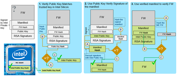
The following three steps are used to authenticate any binary to be loaded during boot flow:
- Verify Public Key. The public key found in the manifest header is hashed and compared with the already-verified public key hash used to authenticate the component. For example:
- Public key in RBE and ROT KM manifest header will be hashed and compared with the public key hash in ROM.
- Public key in OEM KM manifest will be hashed and compared with public key hash in OEM FPF.
- Public key in OEM ISH will be hashed and compared with public key hash for ISH in OEM KM when present there. If it is not present there, the Intel ISH public key in the manifest will be hashed and compared with public key hash for ISH in ROT KM.
- Use Public Key to Verify Signature. Once the public key in the manifest is verified, it is used to decrypt the signature. This produces a hash of the manifest section without the public key and signature. The manifest in the binary is hashed and compared to the decrypted signature output. If these hashes of the manifest are equal, then the manifest has been authenticated.
- Use Verified Manifest to Verify FW. Once the manifest has been verified, anything within it can be trusted, including the hash of the original FW binary. The original FW is hashed and compared with the hash of the FW in the manifest to authenticate the FW. If the hashes are equal, the component is fully authenticated and can be loaded or used to authenticate the next step in the chain.
Intel Platform Firmware Resilience (Intel® PFR)
Intel® Platform Firmware Resilience (Intel® PFR) is a hardware-based solution (based on the Intel® MAX® 10 FPGA) that helps protect the various platform firmware components. Intel is contributing this capability as an available option on our 3rd-Generation Intel® Xeon® Processor Platforms for those looking for an integrated solution that may not otherwise be available from their platform vendor of choice.
Intel® PFR monitors and filters malicious traffic on the system buses. It also verifies the integrity of platform firmware images before any firmware code is executed. And most significantly, Intel PFR can even automatically restore corrupted firmware from a protected, known-good recovery image. Data center owners now have additional options to help protect against permanent denial of service firmware attacks with Intel® Platform Firmware Resilience.
Additional detail may be found at the following links:
Intel® Boot Guard
Intel® Boot Guard (BtG) is a CPU hardware-based root of trust designed to ensure the proper BIOS is used to boot the platform. It does this by executing an Intel-provided authenticated code module (ACM) that runs before BIOS and cryptographically verifies the initial boot block (IBB) of the BIOS before handing control to it. In the case where the IBB fails to verify, Intel Boot Guard prevents the platform from booting to avoid control by a potentially malicious BIOS. Intel Boot Guard is known as a verified boot technology and when implemented helps ensure platform integrity.
The boot profile is one aspect of the boot policy and is used to determine the actions that are taken by the startup-ACM (S-ACM, also known as BIOS ACM). Generally, this involves having the OEM decide whether to have an Intel Boot Guard enforcement profile implemented on the system or not, and whether to perform just a verified boot or both a verified and measured boot in the case where Intel Boot Guard is enabled. The boot profile is also used to determine whether the platform supports Intel® Trusted Execution Technology (Intel® TXT) or not.
Intel Boot Guard uses processor and chipset hardware to authenticate system BIOS. Intel Boot Guard is intended to prevent reprogramming attacks and physical attacks against the SPI Flash.
Boot
The OEM sets Intel Boot Guard policies, and the OEM generates a private/public key pair that is used to sign the Initial Boot Block (IBB). The hash of that public key is added to the OEM KM prior to signing the OEM KM. Note that the OEM Boot Guard key is generated and managed by each OEM, and it is up to the OEM to determine what keys are used in any platform.
Upon boot, the processor launches an Intel-signed Authenticated Code Module (ACM), which loads the BIOS initial boot block (IBB) into the processor cache and authenticates it. The OEM KM is verified using the included public key to verify the OEM KM was signed using the OEM KM private key, and that private key is verified to be authentic by comparing it with the hash stored in the FPF HW. By then comparing the Initial Boot Block (IBB) Boot Guard signing key with the hash in the OEM KM and verifying the signature of the IBB, the integrity of the IBB is verified. Once verified, the boot process continues, and subsequent boot components can be verified.
Policies
Policies are under the control of the OEM BIOS developer to request a certain level of platform protection. Policies are provisioned at manufacturing time, and enforce actions of participating platform components, such as: CPU microcode, Intel CSME, ACM, and BIOS to enable the requested security level.
Intel Boot Guard policies fall into two categories:
- Unalterable (immutable)
- Mutable
Unalterable Policies
Unalterable policies used by the Boot Guard component exist as groups of FPFs which are programmed by OEMs during the manufacturing process. Each FPF group clusters related policies together and can be viewed as HW registers. Initially, during development, these policies may reside in CSE internal non-volatile (NV) variables and are committed into FPFs at the End of Manufacturing (EOM) process. Unalterable policies are not directly accessible by BIOS, but that information is made available by S-ACM via the ACM_POLICY_STATUS register and BTG_SACM_INFO MSR. One exception to the unalterable policy items is the Security Version Numbers (SVN), which is stored in the FPF; however, the SVN may be incremented by the S-ACM under control of the OEM policy.
The most notable policy groups are boot policy restrictions (BP.RSTR), boot policy key (BP.KEY), boot policy type (BP.TYPE), and boot policy key type (BP.KEYTYPE).
Mutable Policies
Mutable policies used by Boot Guard are in the Boot Policy Manifest (BPM). The BPM is one of the chained structures allowing mutable policies to be anchored to a given platform in a secure manner.
Initial Boot Block (IBB) Data Description
The IBB consists of the BOOT_POLICY_MANIFEST_HEADER, the IBB_ELEMENT, and the BOOT_POLICY_MANIFEST_SIGNATURE_ELEMENT. The region from the beginning of the IBB up to, but not including the KeySignature field of the Signature element is included in the signature.
| Field | Size (Bytes) | Description |
|---|---|---|
|
StructureID |
8 |
‘__ACBP__’ |
|
StructVersion |
1 |
10h |
|
HdrStructVersion |
1 |
01h |
|
PMBPMVersion |
1 |
This is the Platform Manufacturer’s version number. |
|
BPSVN |
1 |
Bits 7:4 – Reserved, must be zero |
|
ACMSVN_Auth |
1 |
Bits 7:4 – Reserved, must be zero |
|
Reserved |
1 |
Must be 0 |
|
NEMDataStack |
2 |
Size of data region need by IBB In 4K pages. E.g., value of 1 = 4096 bytes 2 = 8092 bytes, etc. |
| Field | Size (Bytes) | Description |
|---|---|---|
|
StructureID |
8 |
‘__ACBP__’ |
|
StructVersion |
1 |
21h, 23h, 24h |
|
HdrStructVersion |
1 |
20h |
|
HdrSize |
2 |
Total number of bytes in Header (i.e., offset to first element) |
|
KeySignatureOffset |
2 |
Offset from start of Bpm to KeySignature field of Signature Element |
|
BpmRevision |
1 |
This is the Platform Manufacturer’s version number. |
|
BpmRevocation |
1 |
Bits 7:4 – Reserved, must be zero |
|
AcmRevocation |
1 |
Bits 7:4 – Reserved, must be zero |
|
Reserved |
1 |
Must be 0 |
|
NemPages |
2 |
Size of data region need by IBB In 4K pages. E.g., value of 1 = 4096 bytes 2 = 8092 bytes, etc. Must not be zero |
| Field | Size (Bytes) | Description |
|---|---|---|
|
StructureId |
8 |
‘__IBBS__’ |
|
StructVersion |
1 |
10h |
|
Reserved |
1 |
0h |
|
Reserved |
1 |
0h |
|
PbetValue |
1 |
Protect BIOS Environment Timer (PBET) value. Upper 4 bits must be 0. Lower 4 bits contain timer setting. |
|
Flags |
4 |
Control flags |
|
BAR 0 / IbbMchBar |
8 |
Optional first base BAR holding set of configuration registers used to enable DMA protection |
|
BAR 1 / VtdBar |
8 |
Optional second base BAR holding set of configuration registers used to enable DMA protection |
|
DmaProtBase0 |
4 |
Low DMA protected range base |
|
DmaProtLimit0 |
4 |
Low DMA protected range limit |
|
Reserved |
8 |
0h |
|
Reserved |
8 |
0h |
|
PostIbbHash |
Size of (SHA_HASH _STRUCTURE) |
Optional hash (depreciated). Set to TPM_ALG_NULL and 0 size. |
|
IbbEntryPoint |
4 |
IBB (Startup BIOS) entry point |
|
Digest |
Size of (SHA_HASH _STRUCTURE) |
Digest of all Hashed IBB Segments |
|
SegmentCount |
1 |
Number of IBB Segments (Hashed and Non-Hashed) |
|
IbbSegment[SegmentCount] |
SegmentCount * Size of (IBB_SEGMENT) |
Array of IBB Segments (Hashed and Non-Hashed) |
| Field | Size (Bytes) | Description |
|---|---|---|
|
StructureId |
8 |
‘__IBBS__’ |
|
StructVersion |
1 |
20h |
|
Reserved0 |
1 |
Must be 0 |
|
ElementSize |
2 |
Total number of bytes in the element |
|
Reserved1 |
1 |
Must be 0 |
|
SetType |
1 |
|
|
Reserved |
1 |
|
|
PbetValue |
1 |
Protect BIOS Environment Timer (PBET) value. Upper 4 bits must be 0. Lower 4 bits contain timer setting. |
|
Flags |
4 |
Control flags |
|
BAR 0 / IbbMchBar |
8 |
Optional first base BAR holding set of configuration registers used to enable DMA protection |
|
BAR 1 / VtdBar |
8 |
Optional second base BAR holding set of configuration registers used to enable DMA protection |
|
DmaProtBase0 |
4 |
Low DMA protected range base |
|
DmaProtLimit0 |
4 |
Low DMA protected range limit |
|
DmaProtBase1 |
8 |
High DMA protected range base |
|
DmaProtLimit1 |
8 |
High DMA protected range limit |
|
PostIbbHash |
Size of (SHA_HASH _STRUCTURE) |
Optional hash (depreciated). Set to TPM_ALG_NULL and 0 size. |
|
IbbEntryPoint |
4 |
IBB (Startup BIOS) entry point |
|
ObbHash |
Size of (HASH_LIST) |
List of digests of all Hashed IBB Segments |
|
Reserved |
3 |
|
|
SegmentCount |
1 |
Number of IBB Segments (Hashed and Non-Hashed) |
|
IbbSegment[SegmentCount] |
SegmentCount * Size of (IBB_SEGMENT) |
Array of IBB Segments (Hashed and Non-Hashed) |
| Field | Size (Bytes) | Description |
|---|---|---|
|
Size |
2 |
Number of bytes in HASH_LIST structure |
|
Count |
2 |
Number of Digest elements |
|
Digest |
Count * Size of (HASH_STRUCTURE) |
Array of HASH_STRUCTURE digest descriptions |
| Field | Size (Bytes) | Description |
|---|---|---|
|
Reserved |
2 |
00h |
|
Flags |
2 |
Flags indicating the IBB Segment type |
|
Base |
4 |
Physical address of an IBB segment. |
|
Size |
4 |
Size of the IBB segment in bytes (64-byte aligned) |
| Field | Size (Bytes) | Description |
|---|---|---|
|
StructureId |
8 |
‘__PMSG__’ |
|
StructVersion |
1 |
10h, 20h |
|
Reserved |
3 |
Must be 0 |
|
KeySignature |
Size of (KEY_AND_SIGNATURE _STRUCT) |
Intel Boot Guard Policy Example
Using the example IFWI shown in the IFWI Boot Trust Flow section, the Boot Policy Manifest can be located by looking up the FIT type 0ch record address of 0FFFF7e00h. Remember, the structure can be identified with the Structure ID string of __ACBP__. Note that just as above, the format of the structure may change over time. To identify the specific structure format, use the Structure ID and the Structure Version information to properly match the structure format.
In the following example, the Structure Version is 10h. In comparing Boot Policy Manifest structures above, we can identify one key hash (shown highlighted in yellow, below) and the public key (shown highlighted in green below). The signature block for verifying the integrity of the Boot Policy Manifest follows the public key.
ffff7e00: 5f5f 4143 4250 5f5f 1001 1000 0000 4000 __ACBP__......@.
ffff7e10: 5f5f 4942 4253 5f5f 1000 000f 0000 0000 __IBBS__........
ffff7e20: 0000 d1fe 0000 0000 0000 d9fe 0000 0000 ................
ffff7e30: 0000 1000 0000 f000 0000 0000 0100 0000 ................
ffff7e40: 0000 0000 0f00 0000 0000 0000 0000 0000 ................
ffff7e50: 0000 0000 0000 0000 0000 0000 0000 0000 ................
ffff7e60: 0000 0000 0000 0000 0000 0000 f0ff ffff ................
ffff7e70: 0b00 2000 43e0 caa1 9dda c359 645c 7409 .. .C......Yd\t.
ffff7e80: f9b5 ab93 59c3 9634 8bd2 ab09 0351 f931 ....Y..4.....Q.1
ffff7e90: 92b3 25e4 0500 0000 0000 00ce ff00 0003 ..%.............
ffff7ea0: 0000 0000 0000 00de ff00 800e 0000 0000 ................
ffff7eb0: 0000 00ed ff00 0011 0000 0000 0000 00fe ................
ffff7ec0: ff00 7901 0000 0000 0000 84ff ff00 7c00 ..y...........|.
ffff7ed0: 005f 5f50 4d53 475f 5f10 1001 0010 0008 .__PMSG__.......
ffff7ee0: 0100 0100 1315 8420 e2d1 fb84 7e49 a799 ....... ....~I..
ffff7ef0: 4df9 57ef dfcc 975b 8238 aa21 91e9 8c24 M.W....[.8.!...$
ffff7f00: 620d b163 b9d3 4ba8 f1e9 6b40 8ec8 1732 b..c..K...k@...2
ffff7f10: 9132 4c25 ade3 8a3f 2c77 081e 4f19 5501 .2L%...?,w..O.U.
ffff7f20: 12fb 5c90 55e2 e576 42ec c041 1fe7 ec96 ..\.U..vB..A....
ffff7f30: 5f1e ab8f 9c24 d626 90a8 4e3a 51e5 1493 _....$.&..N:Q...
ffff7f40: 1c86 049b 6574 438d 997c 7950 3136 e997 ....etC..|yP16..
ffff7f50: 9192 c66b a8aa 4f7d b77a 760f ba35 2174 ...k..O}.zv..5!t
ffff7f60: b604 8bf5 a082 0c0b 3087 e32f 75d7 2ef2 ........0../u...
ffff7f70: 7ddc 70e8 b280 7d39 f1c4 9140 ec12 5e7a }.p...}9...@..^z
ffff7f80: 445c c722 c780 9e56 3f99 0935 ce33 f8e4 D\."...V?..5.3..
ffff7f90: b25c 4433 fdd7 3d31 ec21 36fd 1206 f196 .\D3..=1.!6.....
ffff7fa0: 78cb cea8 b64c 58c2 b7a8 ddea 5dae e54a x....LX.....]..J
ffff7fb0: 289b 5f6c 8ab8 f869 8d97 7a24 1cbf 74c5 (._l...i..z$..t.
ffff7fc0: b102 ea0e 650b d0d5 405f 6bdc 9bcf ec40 ....e...@_k....@
ffff7fd0: d1dd 6af2 c729 4eb8 80a1 6bcf 8e3b 1c28 ..j..)N...k..;.(
ffff7fe0: 4069 e0e4 1400 1000 080b 006f 100d b515 @i.........o....
ffff7ff0: 67e9 2b64 1a2c b357 0e5f 1775 d871 45ff g.+d.,.W._.u.qE.
ffff8000: 7ff9 7829 38bd 6c06 1193 67f8 e2d9 489c ..x)8.l...g...H.
ffff8010: f946 369e 4923 3449 a0be 0825 2bbf d5ec .F6.I#4I...%+...
ffff8020: 4b2f 5106 09aa 133d b5ba 0aee 23e7 a4a1 K/Q....=....#...
ffff8030: 902b d13a 10c0 403d b1f4 6d47 b34a 3535 .+.:..@=..mG.J55
ffff8040: e86d c8a6 6ae8 5f94 d13e b488 da52 bad1 .m..j._..>...R..
ffff8050: 8c0f dd42 afd9 013b ac28 10ee c524 582f ...B...;.(...$X/
ffff8060: 5ef6 3134 700b db29 02a7 3819 dd1c 48a2 ^.14p..)..8...H.
ffff8070: 8539 20cc b1a9 f307 b3a9 2b66 f220 a5f2 .9 .......+f. ..
ffff8080: 61b5 bd7f 65b9 4b0e 3ecf 7603 bfce 1423 a...e.K.>.v....#
ffff8090: 4f92 562a 43ee 2cac d78d 7dc2 c356 235d O.V*C.,...}..V#]
ffff80a0: facb 686a fd27 78d4 83fc f19d aa30 3b0f ..hj.'x......0;.
ffff80b0: fdc4 6f6a 1fc3 ee10 46f0 2ac7 5597 bc4b ..oj....F.*.U..K
ffff80c0: e5cb 2d72 36b6 2de6 fe64 aa98 7b0e 05f9 ..-r6.-..d..{...
ffff80d0: 8a16 7218 96b7 b3a1 1b6b f522 1884 f1cc ..r......k."....
ffff80e0: fa42 290d 23dd 08bb 7daa fe .B).#...}..
Additionally, to demonstrate the trust linkage between the OEM KM and the Boot Policy Manifest, calculating the SHA256 hash value of the Boot Policy Manifest public key modulus (shown highlighted in bold italic above) results in the hash value that appears in the OEM Key Manifest (shown highlighted in italic below). So, assuming the OEM Key Manifest integrity is intact, and the signature of the Boot Policy Manifest is verified correct, then the continuation of trust now extends to the Boot Policy Manifest since the valid signature would require knowledge of the private keys used to sign the OEM KM and the Boot Policy Manifest.
ffff7900: 5f5f 4b45 594d 5f5f 1010 0001 0b00 2000 __KEYM__...... .
ffff7910: d550 2ff0 6169 9f9e 2b7c 64ab 4137 4f56 .P/.ai..+|d.A7OV
ffff7920: ae6f 45db 870d dba4 733d dc30 3238 78bb .oE.....s=.028x.
Taking a closer look at the IBB structure, we see another SHA256 hash value which, in this case, is a digest of the total IBB segments. The next byte, 05h (shown in superscript below) is the SegmentCount. The SegmentCount indicates the IBB consists of 5 segments, and since all have Flags values of 0, all 5 segments are included in the hash calculation. The Base address (shown in bold italic below) and Size of the segments (shown in bold below) are shown below. When hashing the 5 segments, the resulting value is the hash shown highlighted in yellow below.
ffff7e10: 5f5f 4942 4253 5f5f 1000 000f 0000 0000 __IBBS__........
ffff7e20: 0000 d1fe 0000 0000 0000 d9fe 0000 0000 ................
ffff7e30: 0000 1000 0000 f000 0000 0000 0100 0000 ................
ffff7e40: 0000 0000 0f00 0000 0000 0000 0000 0000 ................
ffff7e50: 0000 0000 0000 0000 0000 0000 0000 0000 ................
ffff7e60: 0000 0000 0000 0000 0000 0000 f0ff ffff ................
ffff7e70: 0b00 2000 43e0 caa1 9dda c359 645c 7409 .. .C......Yd\t.
ffff7e80: f9b5 ab93 59c3 9634 8bd2 ab09 0351 f931 ....Y..4.....Q.1
ffff7e90: 92b3 25e4 0500 0000 0000 00ce ff00 0003 ..%.............
ffff7ea0: 0000 0000 0000 00de ff00 800e 0000 0000 ................
ffff7eb0: 0000 00ed ff00 0011 0000 0000 0000 00fe ................
ffff7ec0: ff00 7901 0000 0000 0000 84ff ff00 7c00 ..y...........|.
ffff7ed0: 005f 5f50 4d53 475f 5f10 1001 0010 0008 .__PMSG__.......
Table of five IBB segments:
Flags: 0000h, Address: FFCE0000h, Size: 00030000h
Flags: 0000h, Address: FFDE0000h, Size: 000E8000h
Flags: 0000h, Address: FFED0000h, Size: 00110000h
Flags: 0000h, Address: FFFE0000h, Size: 00017900h
Flags: 0000h, Address: FFFF8400h, Size: 00007C00h
Initial Boot Block (IBB) is the first piece of BIOS code executed after the Boot Guard ACM has successfully returned control to BIOS at IBBEntryPoint. IBB is responsible for maintaining the Boot Policies, including the Boot Policy Types (that is, Measured Boot, Verified Boot, or both.) IBB has two types: Hashed IBB Segment and Non-Hashed IBB Segment (optional.) Boot Guard ACM will only verify/measure the Hashed IBB Segment(s).
The IBB as a whole is responsible for transferring the contents of next stages of the boot (that is, the Next Boot Block) from the flash into memory. To utilize the hardware root of trust for verification provided by Intel Boot Guard, the platform must continue the chain of trust. IBB is also responsible for maintaining the direct memory access (DMA) protections, if required by platform. Essentially, the IBB should verify and/or measure the Next Boot Block it placed into memory before transferring control to it.
To maintain the Chain of Trust from the Intel Boot Guard hardware-based root of trust through the rest of BIOS code execution, BIOS is required to verify any new block of code prior to executing it. This means that any time BIOS execution moves from one Firmware Volume (FV) to another that has not yet been executed, BIOS is required to verify that new FV comes from within the currently authenticated chain of trust before executing the FV. This is described in more detail within the UEFI Platform Initialization Specification, Volume 3.
After UEFI has completed configuration of the system and setup to enable loading of an operating system, Secure Boot can be used to continue the chain of trust to booting of the OS.
Secure Server Signing
The purpose of this section is to show an example of how OEMs can perform production signing without requiring the signing utility (MEU) to run on the signing server. End customers/ODMs/system integrators are also able to re-sign third-party images without sharing their private keys. OEMs may use MEU to initially debug sign or sign using a placeholder first, and then export the given manifest to a signing server for OEM proprietary signing.
Intel does not support external production server signing.
Production High Level Signing
The secure server is used to insert a production signature and public key hash into the manifest, which can then be imported using MEU to the original binary, thus creating the production signed component.
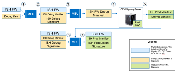
Signing on an OEM Secure Server
This section assumes a configuration where the private keys are stored on a secure server and the build is completed on a non-secure server. The secure server has access to the private keys using a Hardware Security Module (HSM), as an example, but does not share the private keys. A non-secure server (for example, build server) builds the image and does not have access to the private keys.
The following steps would be performed to complete the signing process.
Steps Performed Outside the Secure Server
- Create an IP FW binary signed with a placeholder key. This placeholder key is a local temporary key in the non-secure server.
- Export the manifest section of the binary.
- Parse the IP manifest header and remove the crypto block from the manifest binary. This is done based on fixed offsets or parsing of the binary with a hex editor. No other fields in the manifest should be changed.
- Send the manifest binary (without crypto block) to the secure server.
Steps Performed on the Secure Server
5. Generate the production private and public key pairs.
6. Calculate the signature for the manifest binary (without the crypto blocks).
7. Use a tool, such as OpenSSL, to extract the public key modulus and exponent values.
8. Add new crypto block to the manifest binary, filling in the appropriate data.
9. Send the manifest binary with the updated crypto block to non-secure server.
Steps Performed Outside the Secure Server
10. Generate the production public key hash using MEU tool.
11. Use MEU to import the updated manifest binary to the appropriate FW binary.
Protection of Private Keys
This document presented a high-level view of how private/public keys pairs are used in the Integrated Firmware Image (IFWI). The private keys and cryptographic functions used in hash and signature functions provides a Chain of Trust (CoT) to block updates and detect modifications made to the IFWI by anyone other than the Original Equipment Manufacturer (OEM) or Original Design Manufacturer (ODM). The CoT begins in hardware (HW) and when properly enabled and configured, can ensure firmware (FW) integrity is maintained. Also, the use of multiple keys in the CoT can help to reduce the need to access the OEM KM private key and reduce the overall exposure of any other key in the CoT, if one of those keys becomes known.
However, if a private key becomes known, an unauthorized user may be able to use the key to sign FW code or data structures, and thus may be able to bypass FW protections or to allow modification of FW that could allow malicious software to gain control of the platform. The specific impact of the key exposure will depend on the usage for the exposed private key.
In many cases, if a private key does become known, such as if the OEM Boot Guard key were exposed, the OEM can consider releasing a BIOS update that replaces the exposed key with a new key, re-sign the appropriate structures, and update the appropriate hash values to reestablish the CoT.
It should be noted, however, that if the exposed key is the private key used to sign the OEM Key Manifest (OEM KM), then unless the HW provides a method to disable the exposed key and enable a second key, platforms from that OEM that use the key that was exposed are potentially vulnerable to firmware modification and are not able to reestablish the CoT. It is therefore highly recommended that industry best practices be applied to ensure, at minimum, the OEM KM is properly protected from unauthorized access, such as storing private keys in a Hardware Security Module (HSM) and implementing a signing server as explained in the Secure Server Signing section.
Recent ransomware attacks on some OEMs have involved BIOS source code and build environments being taken that also included one or more private keys for those platforms. To reduce the chances of such exposure, private keys should never be stored with the BIOS source code.
Development and Test Keys
Sometimes, in the development phase for a platform, pre-production test keys may be provided to the OEM to simplify the explanation and demonstration of the process of building an IFWI. Those keys allow the OEM to walk through a demonstration of how the build process works and provide examples of when the process is working correctly. However, when preparing for production, if the OEM fails to generate their own keys to replace these test keys, those OEMs platforms may be exposed to unauthorized FW modification.
Since these development demonstrations are routinely provided to many OEM, ODM, and BIOS vendors for educational purposes, these same keys are available to many people. Also, since these keys are known to be test keys, these keys are not intended to be used in production environments. Therefore, if an OEM/ODM uses a test key in a production platform, the OEM/ODM should be aware that it is using a key that is widely distributed and could be easily discovered.
Firmware Scanning
To inform users of platforms that are potentially vulnerable to firmware modification due to OEMs/ODMs using known keys, some firmware utilities are adding a function that scans system IFWI and FW components looking for the presence of known private keys. These known private key lists are being assembled from preproduction test private keys as well as private keys that are claimed to have been found in various leaks that were posted online. These lists are not created or maintained by Intel, and Intel makes no representations about the accuracy or completeness of these lists.
It should be noted that if a key is detected in an IFWI image or FW update in which that private key is known, the use of that key must be identified to determine if the platform is vulnerable to FW modification. Additionally, there are FW protection technologies that provide “defense-in-depth” through overlapping technologies, such as Intel Platform Firmware Resiliency (Intel PFR) in combination with Intel Boot Guard. In this case of overlapping technologies, the use of a known private key in the FW is blocked from signing FW changes due to Intel PFR protections.
Intel recommends OEMs and ODMs check for known private keys and replace or remove them in their images where possible.